onlym112
Structural
- Sep 9, 2019
- 45
Hello,
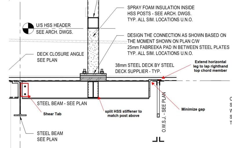
I am currently designing a simple shear connection where one end of a W200x27 beam is welded to an L152x89x9.5 angle which in turn is bearing on a OWSJ flange. Please see attached photo for reference. I am in the process of figuring out the various limit states that I need to check and was wondering what everyone else would consider. I am an engineer-in-training and am just beginning to learn steel connection design. So far these are the following checks that I think are applicable:
Supported Beam:
- Shear Yielding
- Tensile Yielding
- Interaction of Shear and Tensile
Welds:
- Weld resistance to shear
- Weld resistance to axial
Angle:
- Bending of angle leg due to axial
- Bending of angle leg due to shear
Supporting Joist:
- Bearing
- Bending of flange
Is there something else that I need to consider? If so, is there an example or a design clause you could lead me to?
Thank you,