Continue to Site

Eng-Tips is the largest engineering community on the Internet

Intelligent Work Forums for Engineering Professionals

  • Congratulations KootK on being selected by the Eng-Tips community for having the most helpful posts in the forums last week. Way to Go!

Simple Structure Optimization get Twisted ...

Status
Not open for further replies.

yassou

Mechanical
Mar 13, 2015
69
Hello everybody.
I'm working on simple structure from a paper, "On the topological optimization of horizontal links in eccentrically braced frames", That need to be validated.
So far, I think done all steps according to the source paper but still there is something fishy that I can't figured out. So, in order to show you fellow community to what is what I describe the steps in the bellow PDF file Link.
I think the main problem is The Beam (in both of I Shape and Box Shape) did not properly deform and my stress and displacements values (specially in optimization process) are not within a reasonable range.
The only thing that can find in the source paper and don't know where and how should apply it is:
1-
Source-Paper said:
To allow links deformation during the loading procedure, finite deformations are considered in the FE analysis.
Thanx for your contributions.
With best regards.
yassou.
Link
 
Replies continue below

Recommended for you

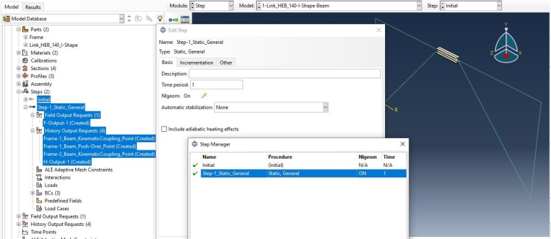
To consider finite deformations you just have to set Nlgeom to On in the step settings.

For easier comparison of your and reference results, you can set the same limits for the scales of the contour plots as the ones used in the article and import their XY plots as "From keyboard" (you will have to read the data points first but there are various small programs that can digitize plots from images).
 
FEA way, Thnx four your respond.
Yes Indeed, And also i did the same thing in my simulation.
3_Abaqus_Step_Manager_kgyh71.jpg

But sadly the output is not the same as The source paper demostrated.
Source paper:
Fig-12_HEB-BeamStress_s5hzjp.jpg

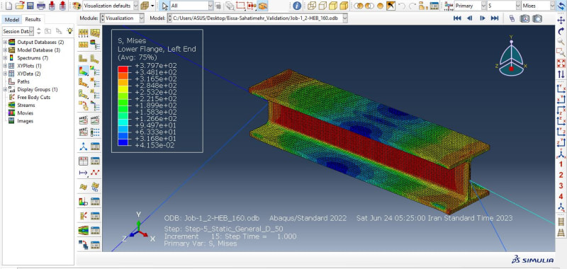
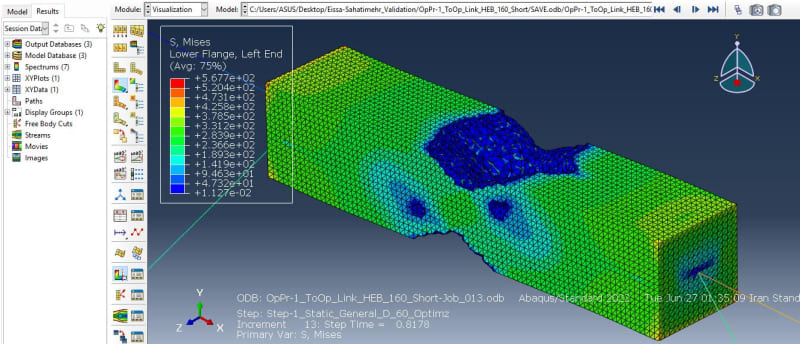
What I done:
8_Resualts_Link_BeamShape_HEB_160_Displace_50_csnuze.jpg

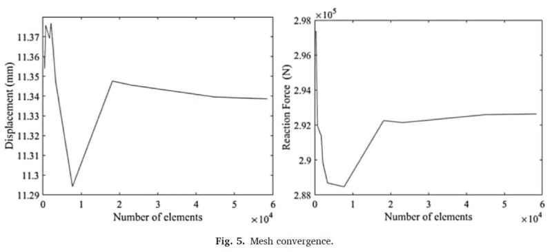
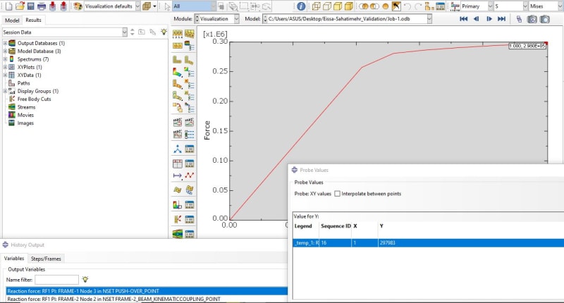
As can seen The amount of the Stress and Deformation did not match. On the other hand Reaction forces in X direction match together !!
Source paper:
Fig-5_Mesh_Convergance_kqm21b.jpg

What I done:
8_Resualts_Link_BeamShape_PushOVerPoint_RF_p70bzl.jpg

So I totally lost what is what ?!
In one of internet pages that have question "How to consider large deformation and finite strain when using UMAT subroutine in ABAQUS?" I saw this sentence:
Abhimanyu Kumar said:
at every increment strain tensor is passed to umat. So if you just turn on nlgeom, then large strain tensor will go. However if your materail calculation is based on small strain, then it's not going to do anything (or might even corrupt the solution)...check out abaqus analysis manula->introduction->syntax and convention->convention
With best regards.
yassou.
 
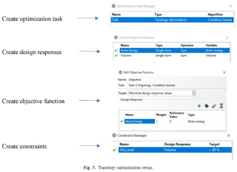
Also in optimization process the amount of Reduction that I done is in accordance with the paper framework, But Results they show is significantly different what it should be ?!
Paper framework for Optimization:
Fig-7_TopologyOptimizationSetup._chiphy.jpg

What I get from this kind of configuration:
8_Resualts_Link_PrismShape_HEB_160_Displace_50_gndiwf.jpg

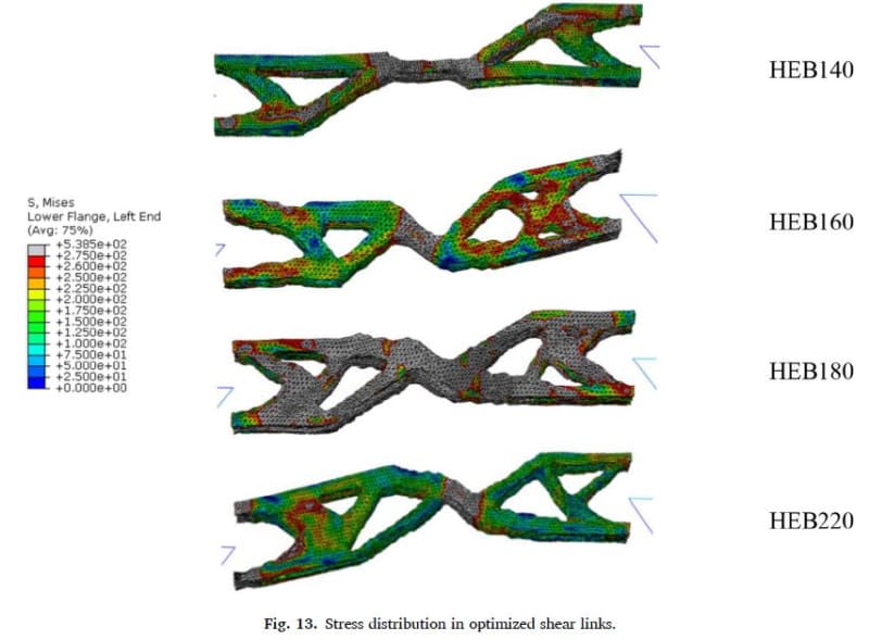
What paper Show as Result:
Fig-13_Stress_distribution_in_optimized_shear_links_lpw56j.jpg

So Confusing !
 
Status
Not open for further replies.

Part and Inventory Search

Sponsor