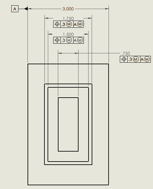
I'm trying to find a simple and effective way to dimensioning symmetrical features. There are many threads on this forum that are discussing about how to correctly dimensioning the symmetrical features. I definitely learned a lot from those.
However, in some cases the part has so many symmetrical features that it is just not effective to put datum reference for all of them. Especially among all the symmetrical features, maybe only one or two are critical. So I wonder is there a simple way to give general tolerance to non-critical symmetrical dimensions? It can be a note or a general profile tolerance in the title block or some thing else.
I attached a sample drawing that have four symmetrical features on the top. As you can see, it took a lot of space which in my opinion, is not worth it. Imagine if you have five, six or more. The whole drawing would be filled with duplicate datum reference frame...

