Does such a thing exist for O2 at high pressure?
Searched this site, and cannot find anything similar.
I have tried several online calculators for same, with results that vary by an order of magnitude... from 22 psi to 322 psi.
On the TLV website calculator (pretty detailed, and the unit analysis worked out), their calc result (200 psi) is a far cry from their formula that I went through (22 psi)...
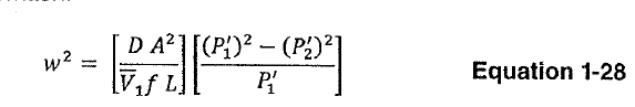
Also tried a couple of the Darcy and Iso compressible flow equations in Metric Crane 410 - I could never get the unit analysis to work out.
Conditions:
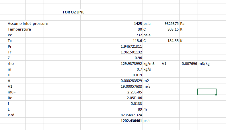
Client needs 0.7 kg/sec@ 1200 psi. Call it 2520kg/hr.
I have assumed to provide that volume at 1300psi to allow for a ...reasonable...pressure drop.
At 1300 psi = 115 kg/m^3 = 7.2 lb/ft^3 density.
after some conversions = 11.7 ft^3/min (0.0054 m^3/sec) mass flow.
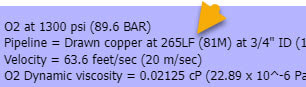
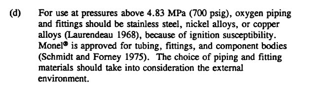
O2 at 1300 psi (89.6 BAR)
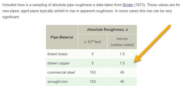
Pipeline = Drawn copper at 265LF (81M) at 3/4" ID (19mm) - pipe and O2 tanks are indoors at appx 70-100F (21-38C)
Velocity = 63.6 feet/sec (20 m/sec)
O2 Dynamic viscosity = 0.02125 cP (22.89 x 10^-6 Pa s)
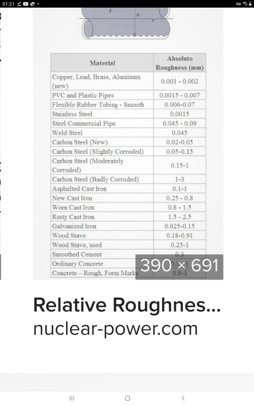
Surface roughness (Epsilon) = 0.0025 mm
Relative Roughness (Epsilon/diameter) = 0.00013
Reynolds #= 2.5Mil, Relative roughness 0.00013, Darcy FF = 0.015
O2 compressibility factor 0.308
O2 molecular weight = 32
Ratio of specific heat "k" = 1.4
Roughness coefficient = 0.0015
Mach # = 0.08; but this was from a site that yielded a pressure drop of 283 psi (???), as well as well as a Reynolds # 2X what I calculated.
A multi-hundred pressure drop for this system just does not feel right...
We have 2-bank O2 Manifold, with H size Cylinders at 2000 psi: so we have lots of P available.
Think I have everything covered above.
I think/thought we fall into the range where Darcy is still applicable; but I cannot seem to make it work.
Can anyone point me to something that has been verified to be reasonably accurate? +/- 10% or so is all I am looking for.
TIA
Searched this site, and cannot find anything similar.
I have tried several online calculators for same, with results that vary by an order of magnitude... from 22 psi to 322 psi.
On the TLV website calculator (pretty detailed, and the unit analysis worked out), their calc result (200 psi) is a far cry from their formula that I went through (22 psi)...
Also tried a couple of the Darcy and Iso compressible flow equations in Metric Crane 410 - I could never get the unit analysis to work out.
Conditions:
Client needs 0.7 kg/sec@ 1200 psi. Call it 2520kg/hr.
I have assumed to provide that volume at 1300psi to allow for a ...reasonable...pressure drop.
At 1300 psi = 115 kg/m^3 = 7.2 lb/ft^3 density.
after some conversions = 11.7 ft^3/min (0.0054 m^3/sec) mass flow.
O2 at 1300 psi (89.6 BAR)
Pipeline = Drawn copper at 265LF (81M) at 3/4" ID (19mm) - pipe and O2 tanks are indoors at appx 70-100F (21-38C)
Velocity = 63.6 feet/sec (20 m/sec)
O2 Dynamic viscosity = 0.02125 cP (22.89 x 10^-6 Pa s)
Surface roughness (Epsilon) = 0.0025 mm
Relative Roughness (Epsilon/diameter) = 0.00013
Reynolds #= 2.5Mil, Relative roughness 0.00013, Darcy FF = 0.015
O2 compressibility factor 0.308
O2 molecular weight = 32
Ratio of specific heat "k" = 1.4
Roughness coefficient = 0.0015
Mach # = 0.08; but this was from a site that yielded a pressure drop of 283 psi (???), as well as well as a Reynolds # 2X what I calculated.
A multi-hundred pressure drop for this system just does not feel right...
We have 2-bank O2 Manifold, with H size Cylinders at 2000 psi: so we have lots of P available.
Think I have everything covered above.
I think/thought we fall into the range where Darcy is still applicable; but I cannot seem to make it work.
Can anyone point me to something that has been verified to be reasonably accurate? +/- 10% or so is all I am looking for.
TIA

![[ponder]](/data/assets/smilies/ponder.gif "[ponder] [ponder]")
")