Continue to Site

Eng-Tips is the largest engineering community on the Internet

Intelligent Work Forums for Engineering Professionals

  • Congratulations KootK on being selected by the Eng-Tips community for having the most helpful posts in the forums last week. Way to Go!

Simpson Strong Wall as a True Portal Frame?

StrEng007

Structural
Aug 22, 2014
507
Does anyone know if a strong wall can be used as a true portal frame? My impression from Strong Wall literature is that it will provide the "equivalent" braced wall requirements per the IRC.

My situation is different, I need to provide a true portal frame where load delivered to the frame comes from a single load at the outside corner of the frame. As in, the top of my portal (along the beam length) is not collecting or dragging loads as you would see along a braced wall line.

I cannot figure out how to actually design one of these frames using the Simpson resources. Any suggestions?
 
Replies continue below

Recommended for you

The beam over the top is still dragging the load to the other side of the portal frame. I don't see this being any different than just regular strong wall design.

Unless you are trying to use the flexural stiffness of the beam it seems like just two shear panels with a drag beam over the top to me?

 
Here in the UK they make two different products - A strong wall which is just an equivalent shear wall on its own and a Strong Portal which connects two of these over an opening with a significant timber header beam that does provide portal action and is moment connected at the tops of the shear walls.
 
A picture might help here, as I am confused as well. Wood portal frames typically have a tested moment capacity that is codified where the beam frames overtop the vertical shear wall element. This is achieved by a large collection of nails into both the shear wall element and the beam element to provide rigidity. Not sure how you would attach the nailing directly into the face of the strong wall, isn't there steel hardware preventing this?
 
It is likely cheaper and easier to just have a portal frame fabricated.
 
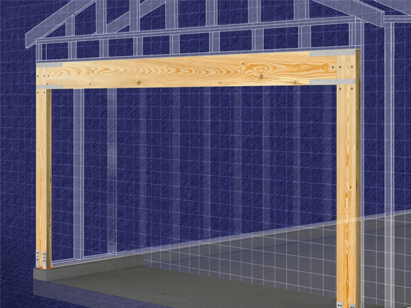
OK, so it looks like I've misinterpreted Simpson's use of the phrase "portal frame"... which would imply flexure maintained between the beam and the top of the wall panel segments.

I was under the impression that the system had moment and was therefore trying to behave as though it were a true portal frame.


pro-lat-sws-pfs-listing-portal-frame-system_lwazvg.png


So in reality, this system provides cantilevered wall segments that don't maintain the typical aspect ratios to shear walls that you'd find in the SDPWS?
 
XR250, OP hasn't indicated, but I'm guessing they have slenderness issues, or the wall system is taller than what portal frame provisions allow.
 
ChorasDen said:
XR250, OP hasn't indicated, but I'm guessing they have slenderness issues, or the wall system is taller than what portal frame provisions allow.

I meant using I-beams not wood.
 
ChorasDen,
I'm using the 2023 version of the Florida Building Code. Our older code used to have provisions for Portal Frames with Hold-Downs, but this has since been reserved. I also believe that I wouldn't have been able to qualify as I'm in a high wind region for this job with winds of 170 MPH.
 
StrEng007 said:
So in reality, this system provides cantilevered wall segments that don't maintain the typical aspect ratios to shear walls that you'd find in the SDPWS?

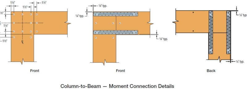
What makes you say that? The beam to column connections sure look like moment connections. And they call them moment connections in their technical literature.

My expectation for how this would have been handled for prescriptive design is:

a) Obtain shear strength and stiffness values for the portals by testing, calculation or both.

b) Reverse engineer imaginary, cantilevered, segmental shear walls with the same shear strength and stiffness as [1] for comparison to prescriptive lateral design methods.

c01_awvoez.jpg
 
KootK,
I agree with you, it's certainly is detailed to look like a moment connection and they call those straps you see "Moment Connection Straps"

However, I don't think I can use this product as intended.

After doing some reading, my understanding is that Simpson has provided this product in order to provide an alternative that meets the prescriptive requirements of the IRC (Section R602.10 Wall Bracing). These prescriptions are limited to 140 MPH.

I was trying to justify if I could use Simpson's values to reverse engineer a solution for myself. But their tables just focus on equivalents, and don't really get into force magnitudes for overall lateral forces. Even if they ARE utilizing true moment frames, it's not like they are saying "this assembly is rated for a lateral load of X pounds", so I can determine the moment at each connections.

 
StrEng007 said:
Even if they ARE utilizing true moment frames, it's not like they are saying "this assembly is rated for a lateral load of X pounds", so I can determine the moment at each connections.

At the risk of being obtuse, have you called simpson to ask for a load rating? They have lots of nice sales people that like to, you know... sell stuff.

I'd bet a thumb that these thing are, in fact, real portal frames.

This would be my last choice in terms of path but I would think that you could:

1) Figure out the length of shear wall that this frame would replace.

2) Work out the capacity of that length of shear wall.

3) Assign that capacity to your portal frame.

The 140 mph thing applies to the method not the components used in the design.

You're FL so it may well be the case that you can't drift this far into judgement land.
 

Part and Inventory Search

Sponsor