FEA_User
Automotive
- Jan 27, 2022
- 29
Hello all,
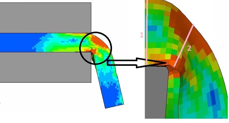
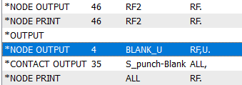
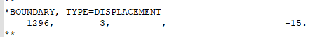
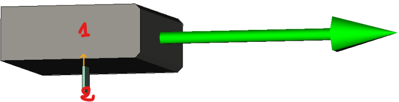
i'm trying to simulate the edge bending of sheet metal using deck abaqus in ANSA but the calculation still diverging,
the error is related to the contact pair "the stimated contact force error is outside of convergence tolerance"
what could be the problem please?
or who can build me a quick model
thanks in advance
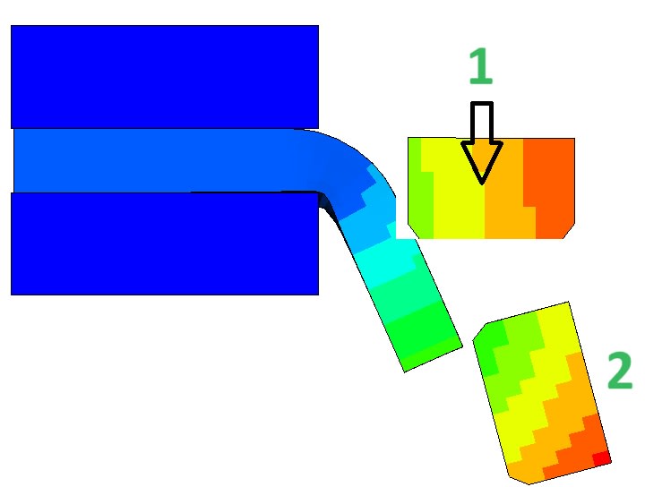
![[thumbsup2]](/data/assets/smilies/thumbsup2.gif "[thumbsup2] [thumbsup2]") thank you very much it's working now, but i still have Two last questions please.
thank you very much it's working now, but i still have Two last questions please.