Continue to Site

Eng-Tips is the largest engineering community on the Internet

Intelligent Work Forums for Engineering Professionals

  • Congratulations KootK on being selected by the Eng-Tips community for having the most helpful posts in the forums last week. Way to Go!

simulation of edge bending

Status
Not open for further replies.

FEA_User

Automotive
Jan 27, 2022
27
Hello all,
i'm trying to simulate the edge bending of sheet metal using deck abaqus in ANSA but the calculation still diverging,
the error is related to the contact pair "the stimated contact force error is outside of convergence tolerance"
what could be the problem please?


or who can build me a quick model
thanks in advance
 
 https://files.engineering.com/getfile.aspx?folder=1ca8a9de-6520-44b5-920e-66eabaadc404&file=Capture_d'écran_2024-04-10_182206.jpg
Replies continue below

Recommended for you

That’s quite thick sheet metal. Which analysis step are you using? For metal forming, typically dynamic explicit analysis is used to avoid convergence issues like this.

Make sure that you have sufficient BCs to avoid rigid body motions if it’s a static analysis. Check the results (stresses, plastic strains, deformations, energies) up to the divergence point. Take a closer look at the contact definition, maybe use general contact. You may need contact stabilization too.
 
@FEA way
Thank you very much for your quick response, i have the same error with static and dynamic/quasistatic analysis
i think the problem cames from the definition of contacts, i don't know what settings to use exactly with contact pair or general contact
please take a quick look to the inp file attached and update it with the right settings according to your experience

thanks
 
 https://files.engineering.com/getfile.aspx?folder=53572ee7-c06e-49ef-a712-602082b16b2d&file=BENDING-INP.7z
What is the purpose of the Beam MPCs here ? If you want to make those parts rigid, just use rigid body constraints for them and apply BCs/loads to their reference nodes. Just be careful what BCs you apply because currently one part is supposed to translate in 2 directions and rotate in 3 directions by 70 mm and 70 rad, respectively for some reason.

Try with dynamic explicit and general contact instead of pairs. It’s easy to set, you can use defaults for everything and just add friction.
 
thank you very much for your help;
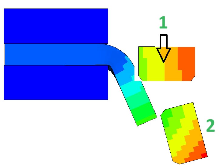
for now it's working but how can I keep the same direction of movement for the punch (1)?
i'm using a general contact with the sheet metal and i'm appliyng a force in the arrow direction but at the end of step the punch fall like the position (2) (see attached )
2_ebeuwq.jpg


thanks in advance
 
Apply a rigid body constraint to the punch and fix all degrees of freedom of its node apart from the one in which the force is acting. It would be better to replace it with prescribed (non-zero) displacement though.
 
thank you again for your reactivity,
that's exactly, what I did, but I think I didn't choose the right contact here I used a surf to surf general contact so i think when the sheet bends the contact acts to pull the punch with the sheet metal
Should i use an edge to edge contact or do you suggest something else?
 
It’s not a fault of contact. If you apply a rigid body constraint to the punch and fix all DOFs of its reference point apart from the vertical one, the punch will only be able to go up and down which can also be controlled with a boundary condition.
 
[thumbsup2] thank you very much it's working now, but i still have Two last questions please.
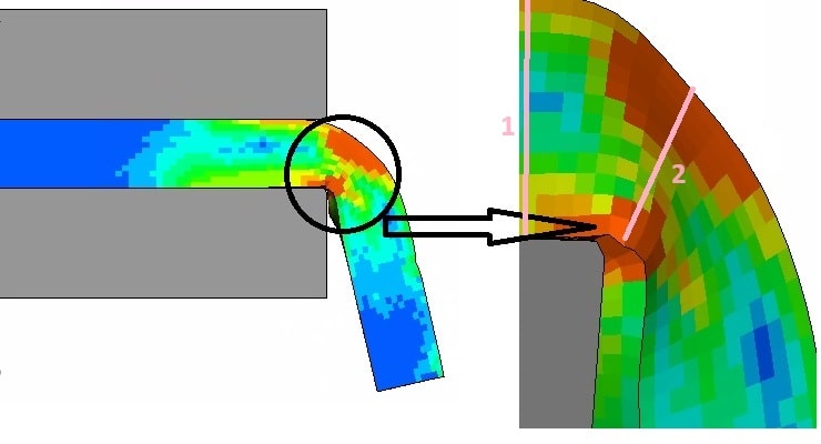
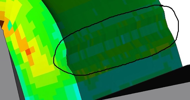
1- How can i keep the same thickness of the sheet metal in the bending zone (LINE 1 = LINE 2)?
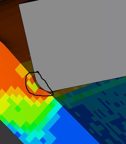
2- how to avoid the deformation of the sheet metal in the contact line with th punch (fig 2)?
thanks in advance

1111111_oqfpv6.jpg

333_xj5zuj.jpg

2222_off5zv.jpg
 
Why do you want the thickness to remain constant? The material will yield when bent like shown, thus reducing the thickness.
 
Those effects don't look like something non-physical so you would have to change the setup to avoid them. What you can do though is make sure that the model is accurate enough - check if there's no hourglassing, refine the mesh and see how it affects the results or even try with different types of elements.
 
i found that the mesh should be more coarser,
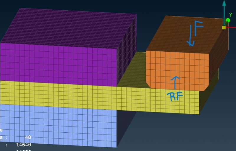
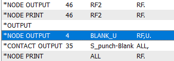
now, please how can i get the reaction force RF of the sheet metal (yello)
i have tried with : *node output, *node print,... but it dosen't work

sssss_bpkvzi.jpg

-----_d4nutg.png
 
Well, rather the opposite - the mesh should be more refined to get better results. Currently, you probably just avoid the local deformation effects by using a mesh too coarse to capture them which is not a good way.

Instead of reaction forces, you should use contact forces from the contact surface. Reaction forces are available only for nodes with a boundary condition in a given direction.
 
Hello;
- I have two parts (1)&(2) connect by a General contact
- initially the component (2) exert a pressure of 20N on the component (1)
- I applied a force on (1)
my questions are:
1- how to model a pressure of (1) on (2) when (2) is moving? can i consider this pressure on the contact definition? If yes how?
2- I tried to impose a displacement BC in (-Z) instead of the force but it doesn't work! is there any problem in the commande line below.:
thanks in advance

rrrrrrrr_srmgxe.png
paaaa_oyeedl.png
 
If there's a normal force between the parts (due to force/pressure applied to one of the components) then it will be visible as CPRESS in contact. You can also include friction in the contact property definition to have shear stresses (CSHEAR).

What do you when saying that it doesn't work ? Is there an error or just a different effect than you would expect ? The syntax is correct if you want the 1296 node to move 15 mm in the negative Z direction.
 
thank you for your assistance:
- when 2 is moving there is a pressure applied from 1 to 2 in the contact surface so: i want to apply a pressure in the contact (as an input) not to read the pressure in the contact
- the simulation finished without problems but the part doesn't move! *i have only one step, should i define the Displacement BC in new step?
 
KCM5 said:
when 2 is moving there is a pressure applied from 1 to 2 in the contact surface

Exactly, the pressure is already there because you defined contact. There’s no need to apply it manually and you can read it as CPRESS.

Regarding the second question, maybe the reference point is not connected to the part or it’s just a matter of visualization settings.
 
ok but what is the default value of the pressure in the contact? i want it to be 20N
 
There’s no default, it depends on the force or pressure applied to one of the parts in contact. Take two cubes, one on top of the other and just push one towards the other with any reasonable pressure you want to use. Then check CPRESS.
 
Status
Not open for further replies.

Part and Inventory Search

Sponsor