Continue to Site

Eng-Tips is the largest engineering community on the Internet

Intelligent Work Forums for Engineering Professionals

  • Congratulations IDS on being selected by the Eng-Tips community for having the most helpful posts in the forums last week. Way to Go!

single phase service to 3-phase motor startup procedure

Status
Not open for further replies.

yaxy

Electrical
Jul 10, 2020
3
We destroyed* the 3-phase pump motor for our neighborhood swimming pool and wonder if the startup procedure we've been using for at least a decade needs improvement.

Property has only single phase 240V service so we have a mechanical phase converter to provide 3-phase power to pump motor. Current procedure is to start the phase converter then a few seconds later close a separate service disconnect switch to start the motor. Phase voltages from converter are 175V, 175V and 5V before closing 2nd switch. Then 240V-260V as expected across each pair.

Does the lower, unbalanced voltages cause stress on the non-rotating motor for those few seconds? If so, would it be prudent to add a device such as a 3-pole contactor that energizes the motor only after all 3 legs are within spec? Does such a device even exist?

If it matters, motor is US Motors/Nidec Motor Corp EEQK1500 (aka Emerson BW37, aka Pentair EQ), 15 HP, 3515 RPM. Phase converter is 21-year-old Gerhard Werner Motor Werke (GWM Corp) WB0304FXA, 30 HP, 1760 RPM.

*Postmortem evidence may make for an interesting investigation into cause of failure.

Thank you for any help/advice!
 
Replies continue below

Recommended for you

Could be wrong, but I don't believe it prudent to start a motor load via a switching device on the load side of a converter / VFD. Transients are produced...

Have you tried having your disconnect closed in, and apply power to your converter?

Mike
 
Good point, and there is no zero-crossing in 3-phase power to eliminate the transients. I was told what you suggest trying (close the second switch before starting the converter spinning with the first switch) could cause damage. I never questioned that advice; maybe I should have.
 
No! NO! NO!! NO!!!!! You NEVER EVER start a rotary phase converter with any trace of a load on it. A 7 Watt night light can be catastrophic to the phase converter.

I watched a 50HP phase converter vaporize because the guy left on a work light on a CNC lathe.

Yes, you always start the RFC first then once it's running for a few seconds you manually or automatically close on the load.

There is a good possibility the RFC had nothing to do with a pool motor dying. They live a short and brutish life.

I think you should try to find out what the phase converter's unloaded output terminal voltages are expected to be. I'm having problems understanding why the two direct connected phases are not precisely your facility's line voltages since they're usually directly connected with only the wonky generated third phase being odd.


Keith Cress
kcress -
 
Thanks Keith...learn something new every day.

Mike

Mike
 
Have you checked the capacitors?


Bill
--------------------
"Why not the best?"
Jimmy Carter
 
Mike; I was dumbfounded to learn that. I learned it the hard way except I got lucky enough that only 'some' smoke was released. The 50hp guy.. not so lucky.

Keith Cress
kcress -
 
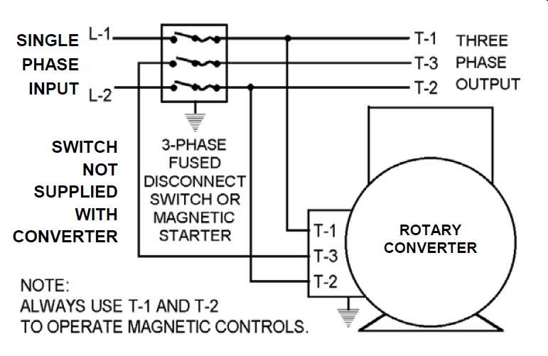
smtp-wiring-diagram-basic-electronics-wiring-diagram_wh1gll.jpg


Note that this is the typical RFC hook-up. See how L1 and L2 literally connect directly to the load side of this pseudo 3 phase? How can they only measure 175V?

Keith Cress
kcress -
 
Keith,
Just being pedantic here, but “RFC”? Rotary Fase Converter? Methinks it should be RPC.

Or are you thinking Rotary Frequency Converter, which is a different device?

Other than that, you are dead on. I interpreted his 175-175-5V measurements with the load disconnected as L-G, not L-L by the way.

Yaxy,
“240-260V” is a problem here. For a 3 phase output, assuming you had two that measured 240 and one that measured 260, that’s a voltage imbalance of a little more than 5%, which is going to create severe current imbalance and extra motor heating. That is the more likely cause of your motor failure. The RPC typically has what are called “balancing capacitors” inside somewhere. It’s possible that one of them has failed or it was never done right from the beginning. People who use RPCs for shop machinery that only runs for short periods of time can get away with not paying attention to that, but for something like a swimming pool motor, it’s critical.


" We are all here on earth to help others; what on earth the others are here for I don't know." -- W. H. Auden
 
LOL, I phake myself out!

Jeff it's hopeless, for some reason I always go for 'RFC' when I don't it's because others have already correctly used RPC and as I re-read my post I catch it.

It's from my 'electronics' base. I have to use RFC, 'Radio Frequency Choke', on schematic layouts frequently. Thanks for pointing it out.

Keith Cress
kcress -
 
Important takeaway from "a rotary phase converter must start first before a load is applied." So we've been very lucky and/or the GWM is very robust.

Caps were recently replaced not necessarily because they needed to be, but out of desperation trying to fix another problem. Hint: Fused service disconnects with steel knives/jaws and damp locations may not play well together.

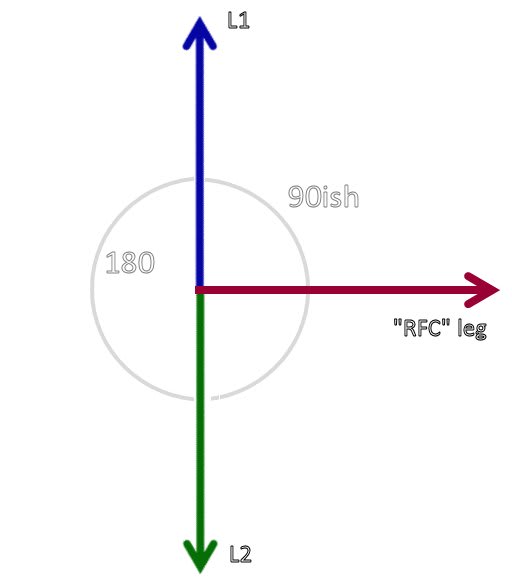
Not sure why I was getting 175V-175V-5V then 240V-???V-260V. Haven't looked at the guts but maybe it's not "typical." Wouldn't that arrangement result in this phasor diagram...

Image3_cbsnno.jpg


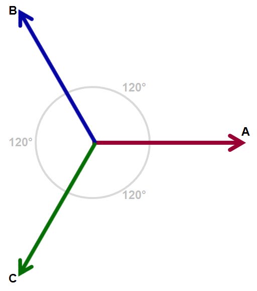
...instead of the theoretical...

Image2_ssjd8l.jpg


?

I don't have a 3-input oscilloscope to drag down to the pump room but would be an interesting Arduino project to see the waveforms.
 
Your motor has no connection to the center tap or neutral connection.
If your RPC leg is extended until it is 0.866 times the value of L1 to L2, you will have balanced three phase.
The motor will not know the difference.
It is called a tee connection.
At one time tee connected transformers of about 25 KVA or 37.5 KVA were widely usedd to transform three phase 480 Volts to three phase 120/208 Volts for lighting panels.
There was a tap on the horizontal section to supply a properly positioned neutral.
The idler motor of the RPC does a good job of producing almost balanced three phase.
The capacitors help.
Hint: If you spin up a three phase motor with a single phase motor before energizing it it many will work almost as well as a RPC.

Bill
--------------------
"Why not the best?"
Jimmy Carter
 
Have you checked the windings in the idler motor?
Those voltage readings may be trying to tell you that it is in trouble.

Bill
--------------------
"Why not the best?"
Jimmy Carter
 
You'd probably find a fairly short payback is possible by switching to a VFD and it would also be much kinder to the motor, and possibly the utility.

 
Re:VFD.

Generally true, but now, swimming pool motors must have GFCI protection, and VFDs do not play well with GFCIs.


" We are all here on earth to help others; what on earth the others are here for I don't know." -- W. H. Auden
 
Jeff. Seeing as there is an idler motor on site;
If the idler motor is driven with aslightly oversized VFD, can a second motor be switched from that or will the VFD still be unhappy?

Bill
--------------------
"Why not the best?"
Jimmy Carter
 
??? Bill.. Why would you drive a RPC with a VFD??
2hgeq95.gif


I think L.H. was suggesting dumping the RPC entirely which is a great idea for a motor that small except in this case for the GFI requirements.


Keith Cress
kcress -
 
I doubt a 15HP, 3-phase motor is plugging into a GFCI receptacle. I believe the code says any cord connected pump or hard wired single phase pump requires a GFCI if the circuit is 20A or less. A 15HP motor will be over 20A, and it's not single phase. The supply being single phase may over ride the pump being single phase though.
 
Status
Not open for further replies.

Part and Inventory Search

Sponsor