Continue to Site

Eng-Tips is the largest engineering community on the Internet

Intelligent Work Forums for Engineering Professionals

  • Congratulations SSS148 on being selected by the Eng-Tips community for having the most helpful posts in the forums last week. Way to Go!

Sister Wood Joist with LVL 3

Status
Not open for further replies.

RM87

Structural
Feb 19, 2013
52
Hello folks,

I've been working on some calcs and I was hoping to get your take on the following issue:

I have an existing 2X12 douglas-fir wood joists supporting the roof.
My clients want to convert the use of the roof, and want to strengthen the joists to accommodate the larger live and dead loads. Existing roofing is to remain.
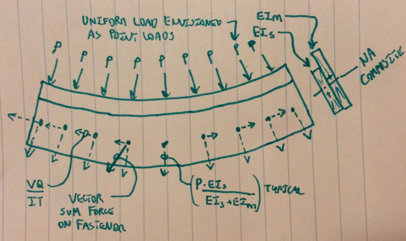
I've been thinking to sister a smaller 1.75X9.5 LVL 2.0E joist to the 2X12 would be a good alternative - flush at the bottom face of the joists.

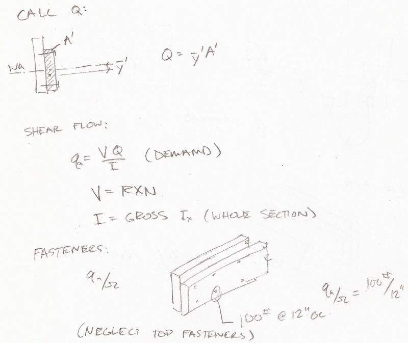
How would you calculate this system? How would you design for the shear flow into the lag screws?

- Rod
 
Replies continue below

Recommended for you

They about the same stiffness. As long as the LVL has bearing at each end, I would just use the uniform load as the shear. (2)10d @ 12" o.c. oughtta be plenty.
 
I wish I felt the same - I'm not entirely sure: E(min-max) = 470-1300 ksi (DF) vs 1017-2000 ksi (LVL)... That strikes me as a relatively significant difference? And yes, the LVL will have bearing at each end.
 

That could be tricky. However, there is a way to make the results more predictable by making the composite beam symmetrical. Create a flitch beam by sandwiching the 2 x 12 between a pair of LVLs. Use through bolts, not lag screws.

A traditional flitch beam has a steel plate sandwiched between a pair of wood beams, but there is no "rule" that says those two materials have to be used. The math is the same, just the material properties differ.

[idea]
[r2d2]
 
Can you put the new LVL flush with the sheathing such that it picks up load directly from the sheathing? Then I would try to match the EI. Using an LVL with a higher E but lower I. This way, you aren't relying on a composite beam as much.
 
I wish I felt the same - I'm not entirely sure: E(min-max) = 470-1300 ksi (DF) vs 1017-2000 ksi (LVL)... That strikes me as a relatively significant difference? And yes, the LVL will have bearing at each end.

You have to look at EI which will even things out a bit. I would think you would know the E of the DF a little better than you have stated. This is commonly done with nails, no lags or thru bolts req'd. It is unlikely you are transferring more than 100 plf thru your connection.
 
I would calculation shear flow as below, but this may be too conservative. And I agree with XR250 in that you should use nails. Wood is great with lots of low strength fasteners. Using wood screws at ends may be a good idea to prevent the material separating.

PhotoScan_xwantt.jpg
 
I don't know if I would even bother with a "shear flow" calc on this. The neutral axes are close enough in my book that I would only look at the relative stiffnesses of the members and transfer the load in proportion to that. Actually, I would just put the entire load into the connection and not worry about it.
 
You're right that you should include vertical shear, and horizontal shear forces should be small.
 
You don't need shear flow. You are only enforcing vertical compatibility. Think about if at each lag (or nail) you had a tiny horiz slotted hole, it would still work the same as the two members would have compatible deflections.

If you have end bearing at the LVL then just give it the relative portion of load as xr250 said. If you don't have end bearing it's a bit different.
 
Firstly, what I would do in practice is the method that XR250 / Bookowski have proposed above. I find this to be an interesting theoretical problem, however, so I'm going to delve a little deeper into what is surely "over thinking" territory.

1) I feel that the simplified sketch below represents the real mechanical situation. Fastener shear, in a purely elastic system, would be a superposition of vertical shear transfer forces and VQ/IT forces.

2) In reality, dowel connections are pretty ductile. As a result, I think that it's pretty safe to simply design the fasteners for the vertical shear transfer force, ignoring VQ/It forces. Connection ductility effectively provides the horizontally slotted holes in Bookowski's analogy. From a member design perspective, this implies designing the two parts non-compositely which is usually the intent anyhow.

3) For the case under consideration, and indeed for most sistering scenarios, I believe that it would be un-conservative to design for VQ/It while ignoring the vertical shear transfer. As XR250 and RPMG have pointed out, VQ/It won't add up to much in these situations. Designing for horizontal shear only may produce a design that isn't even as competent as the two members acting non-compositely.

I have a tidbit of practical advice to offer as well. If nails are used as the fasteners, instead of lag screws or through bolts, I would ensure that they are clinched. The new side member will tend to laterally torsionally buckle on its own and it will be the fasteners acting in withdrawal that will prevent this.

Capture_nmegwk.png


I like to debate structural engineering theory -- a lot. If I challenge you on something, know that I'm doing so because I respect your opinion enough to either change it or adopt it.
 
Very nice analysis KootK.
Assuming (2)10s @ 12" o.c., you have about 50 plf or so withdrawal capacity - probably enough to keep the LVL stable. I wonder if the shear in the nail adds to the withdrawl capcity?
 
Thanks XR250. I would have thought that withdrawal would improve in the presence of shear. For shear parallel to grain, you'd wedge the nails in there a bit better. For shear perpendicular to grain, you'd push harder against some fivers while pulling away from others.

The NDS gives an interaction equation for shear plus tension which seems to imply a reduction. Link

I like to debate structural engineering theory -- a lot. If I challenge you on something, know that I'm doing so because I respect your opinion enough to either change it or adopt it.
 
What's strange about this problem is that if you put little horizontal slotted holes it seems that you would get the same behavior, compatibility is still enforced so you should get the same load sharing.
 
@Bookowski: There's actually a little more to the story than I indicated in my previous sketch. It takes us way down into deep sea over thinking however.

bookowski said:
What's strange about this problem is that if you put little horizontal slotted holes it seems that you would get the same behavior, compatibility is still enforced so you should get the same load sharing.

I don't think that you would get quite the same load sharing in the absence of the little slotted holes. Imagine a free body diagram of the main member with just the inward pointing VQ/IT horizontal nail shears acting on it. It would arch the main member upwards without affecting the support reactions, a bit like PT balancing loads. The side member, however, would tend to resist the upwards arching of the main member.

The net effect of this is that the vertical load sharing that I indicated in my sketch (EI ratios) wouldn't be quite right. Somewhat more load would be carried by the main member. I know, it's a bit ridiculous how complex this gets. And we haven't even touched on baked in the cake, existing loads effects.

I like to debate structural engineering theory -- a lot. If I challenge you on something, know that I'm doing so because I respect your opinion enough to either change it or adopt it.
 
Although you lose a little stiffness, if you put the LVL high and nail it off to the floor diaphragm, the existing joist will take the dead load with no shoring assumed during the LVL installation, and they will share any live load based on their EI ratios. VQ/IB falls out of the picture. Just seems simpler to me.


Mike McCann, PE, SE (WA)


I'm not convinced. It seems to me that if you can enforce compatibility between the two then you know the forces in each (assuming all elastic etc) since they have the same curvature. If there were horizontally slotted holes I think you've still got compatibility...
 
Continuing the overthinking category.....the different sections and EI will cause lateral torsion in the weaker member.
 
bookowski said:
since they have the same curvature.

This statement is true if, and only if, the centroids of the main member and side member are at the same elevation. And in that case, there would be no VQ/It nail shears.

Because the centroidal axis of the side member is on the convex side of the main member centroidal axis, the radius of curvature is greater for the side member than it is for the main member given equal vertical displacement. Larger radius of curvature = less curvature = less load resisted by the side member. And that is consistent with my conclusion above that the main member will carry more than its EI ratio load share as a result of composite behavior and the VQ/It nail shears.

I like to debate structural engineering theory -- a lot. If I challenge you on something, know that I'm doing so because I respect your opinion enough to either change it or adopt it.
 
Status
Not open for further replies.

Part and Inventory Search

Sponsor