Eng-Tips is the largest engineering community on the Internet

Intelligent Work Forums for Engineering Professionals

Size, Rule #1, and parallelism 2

Status
Not open for further replies.

Burunduk

Mechanical
May 2, 2019
2,335
0
0
IL
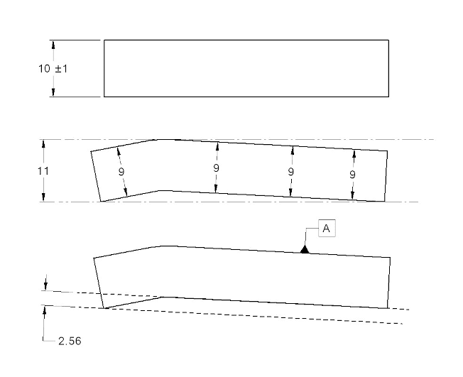
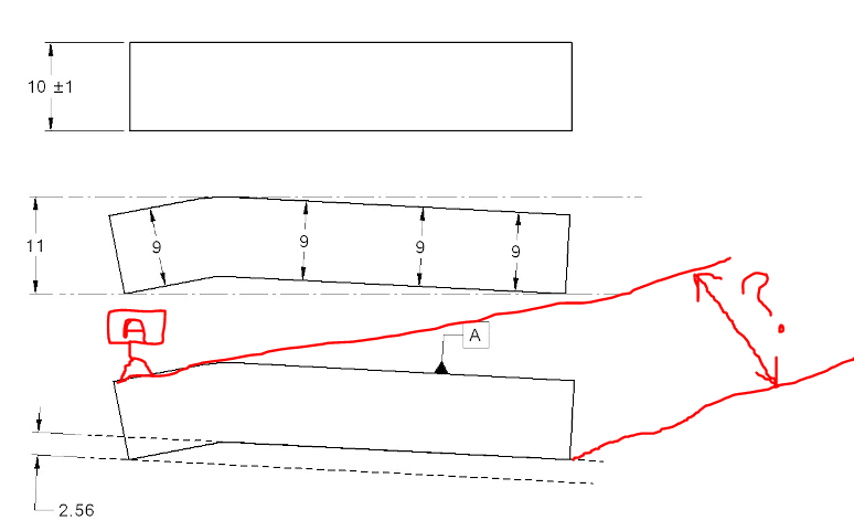
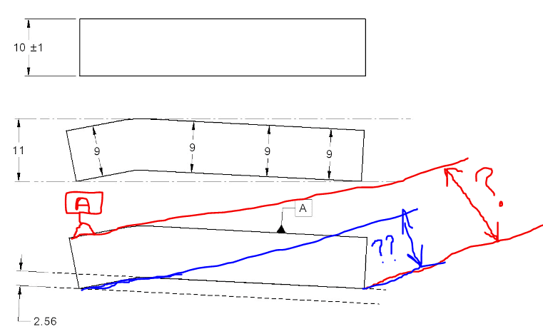
A lot has been said about how a size tolerance with Rule #1 limits the form of a regular feature of size. It is not mentioned in the Y14.5 and related standards or other sources I came by (except a couple of threads in this forum) that, unless it is an oversight, Rule #1 also limits the parallelism error of each face of a width relative to the opposing face. Unlike for example, for flatness applied to a surface, the standard does not instruct us to always specify a parallelism tolerance smaller than the size tolerance associated with the FOS the surface is part of (of course I mean cases when the datum feature is one face of the width and the controlled surface is the other).
Does anyone have any assumptions why the indirect parallelism control by Rule #1 so rarely gets any attention, and why there is no corresponding guidance on non-redundant parallelism tolerance values?
 
Replies continue below

Recommended for you

The general rule is "Limits of size do not control the orientation or location relationship between individual features."
Think of a hole with perfect size and form but badly oriented.
I guess the committee didn't want to open associated can of worms. Every situation where Envelope rule may indirectly control orientation should be considered individually and not made into universal rule.
(Just like datum shift that may or may not contribute to "bonus" tolerance).
Just my 2 cents, and I am interested to see other opinions just like you are.


"For every expert there is an equal and opposite expert"
Arthur C. Clarke Profiles of the future

 
OP said:
...the indirect parallelism control by Rule #1...

Because this fact is just a consequence and outcome of the rules provided by the standard. There are many consequences of such where the combinations of size and geometric tolerances are used. The standard give you the rules and that’s up the individual users to interpret and use them accordingly.

 
CH and greenimi,
Thank you both for the input.
I understand how associating Rule #1 with an orientation control can become a can of worms. This makes sense.
 
Burunduk and All,

I suppose that the main reason that indirect parallelism control provided by Rule #1 is not discussed is because parallelism would seldom be applied to the individual surfaces of a width feature. The indirect form control is much more relevant, because specifying form tolerances is much more common.

Another reason is that the worst-case parallelism variation allowed within the size and Rule #1 requirements would be complicated to calculate and somewhat unrealistic. I haven't really thought it through, but I believe that the worst possible parallelism variation would just be equivalent to the size tolerance. This would occur if one face had a combination of tilt and form error, that corresponds to the other face in the right way (so that the local size does not go outside of the allowable range). Another complication is that either face of a width feature could be used as the datum feature, meaning that the parallelism value "in the other direction" would be different (and possibly even zero).

I believe that the statement that CH referenced about limits of size not controlling the orientation or location relationship between individual features was intended to apply to multiple features of size (e.g. size tolerances do not control the coaxiality of features that are nominally coaxial). It probably was not intended to apply to the two planar surfaces within a width feature.

There is only one example (that I can think of) in Y14.5 that involves an orientation refinement within a size tolerance, and it doesn't mention indirect control. This is Figure 8-27 in 2009 or Figure 11-32 in 2018. Unfortunately the characteristic is profile of a line, but it is described as controlling the orientation of each line element (in other words, it does the same thing as a parallelism tolerance would). The profile of a line tolerance is smaller than the size (height) tolerance in the example, but there is no mention of indirect orientation control provided by the size tolerance.

Evan Janeshewski

Axymetrix Quality Engineering Inc.
 
AXYM,
Could you please elaborate how TWO planar surfaces are not INDIVIDUAL features? I feel like I am missing something.


"For every expert there is an equal and opposite expert"
Arthur C. Clarke Profiles of the future

 
The standard is silent on the enumeration of features.

Potentially any surface could be considered an infinite number of features, but typically the recognition of a feature only happens when there is an arrow or some other indicator pointing at it, usually with a tolerance or datum feature symbol in tow. Each linear element, each point, each radial element, et al, can be a feature. Any combination of points, linear elements, planar or curved surfaces of any grouping can also be counted as a feature, if there is a reference as such.
 
Evan,

axym said:
This is Figure 8-27 in 2009 or Figure 11-32 in 2018. Unfortunately the characteristic is profile of a line, but it is described as controlling the orientation of each line element (in other words, it does the same thing as a parallelism tolerance would). The profile of a line tolerance is smaller than the size (height) tolerance in the example, but there is no mention of indirect orientation control provided by the size tolerance.

Evan,
Do you "like" fig 8-27 /2009 or 11-32 /2018?
If you do, could you, please, explain why profile of a line has been used instead of parallelism?
Not sure I am getting your point about those two figures.

 
CH,

I would say that two planar surfaces are individual features, even when they are part of a feature of size (parallel-plane width feature). What I meant in my comment was that the Y14.5 members probably did not have this case in mind when they wrote the statement that you quoted - they were probably thinking only of the relationships between features of size. So the Y14.5 statement "Limits of size do not control the orientation or location relationship between individual features" is not correct for the case of the two planar surfaces in a width feature. We can show that the limits of size (and Rule #1) do in fact control the orientation and location relationship between the two planar surfaces (which I agree are still individual features) in a width feature.

greenimi,

No, I do not like the "Profile of a Line and Size Control" example - I think that it's problematic. Mixing directly toleranced dimensions with profile tolerancing has led to many arguments on meaning (including many on this forum). I also disagree with Y14.5's use of profile of a line to replace element-based orientation tolerances. The definition of profile of a line still has some major gaps, relating to the direction of the tolerance zones and the effect of datum features. In every example, the effect of location control is overridden in some way. Put it this way - in Y14.5.1 we haven't been able to develop logical rules and math to describe the way that profile of a line currently works in the Y14.5 examples.

Evan Janeshewski

Axymetrix Quality Engineering Inc.
 
Axym, I'm trying to understand a couple of statements that you made (in your first post of this thread).
You wrote that "...parallelism would seldom be applied to the individual surfaces of a width feature." But that's the overwhelming majority of cases that I've seen; the classic example is Fig. 9-2 from 2018.
You also wrote that "There is only one example (that I can think of) in Y14.5 that involves an orientation refinement within a size tolerance," that being the profile example of Fig. 11-32. But wouldn't Fig. 9-2 count as an orientation control that refines the size tolerance of 0.5 mm?
 
Garland23,

You're absolutely right about Figure 9-2 - I didn't even think of that one. I guess I should have actually looked in the orientation section ;^). For some reason I was thinking of smaller parallel-plane slots or tabs. But the 22.6-22.9 height is indeed a feature of size and it is common to see this on drawings. Sorry, I was out to lunch on this one.

Evan Janeshewski

Axymetrix Quality Engineering Inc.
 
Garland23, Evan,
I agree that parallelism in combination with a size requirement similar to fig. Fig. 9-2 from 2018 is not uncommon. Often the parallelism tolerance value is smaller than the size tolerance, and then it does make sense as a refinement of mutual orientation and form. But at other times, redundant parallelism requirements are specified because of designers not being aware of the effect of rule #1 on mutual orientation between the parallel faces of the FOS.

Evan said:
I haven't really thought it through, but I believe that the worst possible parallelism variation would just be equivalent to the size tolerance

This is how I always perceived it, too.
Suppose that at one end of the feature the local size is at MMC and on the other end it is LMC. We know that the surfaces can't violate the MMC perfect form boundary anywhere in between. I think it is the extreme case for the maximum possible parallelism variation, which matches the size tolerance value. Can anything else be true?
 
This quasi-parallelism error between two nominally parallel faces can exceed the size tolerance, even while local size requirements and rule #1 are satisfied.

Imagine if the local size was near the smallest allowed, everywhere. Also, imagine if the part was "maximum banana" and barely conforming to the rule #1 envelope. As Evan points out above, the error would depend on which side was the quasi-datum for our quasi-parallelism measurement.

The first example that came to my mind was a very shallow tent shape, as if a perfectly flat and parallel plate had been creased. Pick one of the resulting faces on the convex side of the tent as your quasi-datum. Move the crease around and see what happens.

quasi_parallelism_vx0k3i.png


Edited to add a (blurry) image.
 
Nescius,
Thank you for the interesting observation and the clear figure you posted.
At first, I was not sure that datum A establishment at that orientation is valid because, effectively, only part of the surface is used as the datum feature.
However, the part may be stable and not rock when datum A is simulated, and therefore a stabilization procedure may not be required.
In that case, you are correct that the quasi-parallelism can potentially exceed the size tolerance. I will remember that for future reference.
 
What about if datum feature A is chosen the small feature?
qpt_-_Copy_ub7whs.png


Q 1: What now should we understand that the maxmum parallelism could be?
Q 2: what is the maximum dimension with question mark "?"
 
And one additional question:
Should I understand that what I marked with double question marked (in blue) represent the maximum parallelism error between "the short" datum A and the concerned feature?

Capture_-_Copy_vdqst6.png
 
Nescius,

Your sketch is intriguing and disturbing. The parallelism is indeed larger than the size tolerance.

greenimi,

The Y14.5.1 standard defines a restriction on the allowable datum planes in situations like this. There is an arbitrary "one third rule". If the length of the datum feature is L and is divided into 3 regions of length L/3, the contact points for the datum plane cannot all be in one of the end regions. In other words, the contact points cannot all be within a distance of L/3 from one end of the feature. So in Nescius's figure the "long" Datum A is allowable but the "short" Datum A is not.

Evan Janeshewski

Axymetrix Quality Engineering Inc.
 
axym said:
Your sketch is intriguing and disturbing. The parallelism is indeed larger than the size tolerance.

Are we sure the sketch posted by Nescius is a correct one. I don't have this week CAD available to verify and replicate the culprit.
Anyone can evaluate the outcome.


greenimi, in addition to what Evan wrote, even if the small portion was somewhat greater than 1/3, datum A simulation tangent to just that portion of the surface would not be stable and would require a stabilization procedure - the single solution that minimizes the distances from the simulated datum to the datum feature per Y14.5-2018. That way the parallelism error wouldn't be allowed to be nearly as great as in your second posted image (the one with the zone size shown in blue).
 
The 1/3 rule is not part of ASME Y14.5.1-2019 and ASME Y14.5-2018 says to minimize per ASME Y15.4.1M-1994, which does not include a minimization method.
 
Status
Not open for further replies.
Back
Top