Continue to Site

Eng-Tips is the largest engineering community on the Internet

Intelligent Work Forums for Engineering Professionals

  • Congratulations KootK on being selected by the Eng-Tips community for having the most helpful posts in the forums last week. Way to Go!

Sliding bearing between deck and supporting beam?

Status
Not open for further replies.

MGaMart

Structural
Aug 23, 2016
50
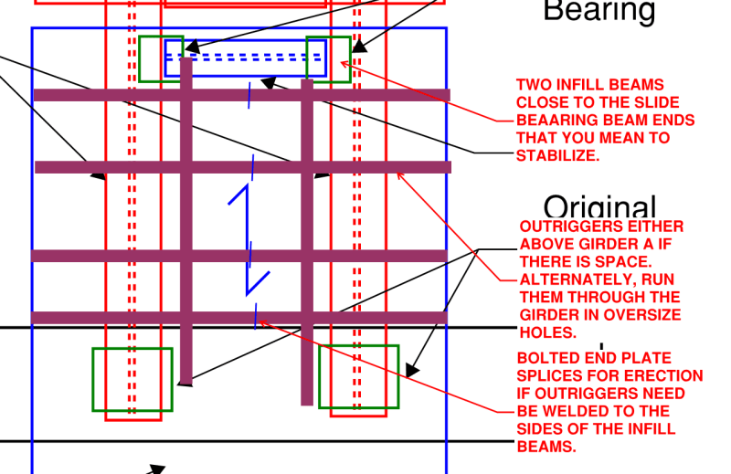
I've come across an unusual situation (at least for me) where the framing is requiring a sliding bearing to exist between the deck and the beam that supports the deck. The back story, it's a pedestrian bridge between two buildings. The attached sketch shows the framing situation. Beam A rests on a sliding bearing but the movement joint is not permitted to be located at the end of Beam A (where it would have been most optimal). The ends of Beam B and Beam C connect into Beam A (two 'Beam A' beams make up the primary girders of the pedestrian bridge), and the movement joint is located between Beams B&C. The deck bears on Beam C and needs to be designed to accommodate the movement of Beam A as it translates in the one direction (parallel to Beam A's longitudinal axis). Has anyone come across this situation before? I'm not a big fan of simply greasing the beam. The framing configuration (i.e. movement joint) cannot be changed (already had a number of meetings with the consulting firm and they need it to stay where it is for architectural reasons). The only solution I've come up with is to 'detach' Beam C from Beam A and introduce a seated bracket with a sliding bearing on each Beam A that would then support Beam C. The deck could then be properly fastened to Beam C. It would add two additional sliding bearings to the bridge, but would shift the relative movement away from the deck which is the crux of this issue. If any of the deck flutes that are supported by Beam C happen to make contact with the top flange of Beam A, my potential solution breaks down in tremendous fashion. I should also point out that the deck does cantilever about a foot beyond the edges of Beam A which further discounts my solution. I just wanted to throw it out to the Eng-Tips community to see if any other more elegant solutions exist.
 
 https://files.engineering.com/getfile.aspx?folder=44608774-4cb2-480c-a7f6-7f00f91f2c5b&file=Deck_Sliding_on_Beam.pdf
Replies continue below

Recommended for you

I like your idea, probably with a couple of infill beams running between the ends of beam C and the curb for stability. Maybe girder A could be dropped an inch to keep it from binding up with the deck?
 

The deck shall not touch beam A but can touch and be supported by beam C which is supported by beam A ..A Strange situation..

I am not sure if you considered as one of the options but i will suggest ; relocate the movement joint such that , the deck could be cantilevered from the bldg floor at right side. The cantilever reinf. would be rebar not mesh.With this option you will not need Beam C.


Thanks for the suggestions thus far. The infill beam for added stability of Beam C is a good idea. I also pondered whether lowering Beam A to create a physical separation with the deck would be viable. At this time I don't see a major problem with that. It unfortunately doesn't address the support needed beyond the two Beam A beams where outrigger members are required to properly support the deck (which is cantilevered in its weak axis about 1-2 feet beyond Beam A). The consultant firm has also declined to switch the deck orientation to have the deck's strong axis in the cantilever region (i.e. the deck would bear on Beam A rather than Beam B&C). @HTURKAK, unfortunately no, the movement joint can't be relocated (already fought and lost that battle) to employ your suggestion of cantilevering the deck and removing Beam C.
 
MGaMart said:
It unfortunately doesn't address the support needed beyond the two Beam A beams where outrigger members are required to properly support the deck (which is cantilevered in its weak axis about 1-2 feet beyond Beam A).

Perhaps you can arrange things such that those outriggers are welded to the top of those new infill beams such that they would pass over girder A? Maybe small HSS outriggers?
 
KootK, I'm not sure I fully grasp the framing you're suggesting. I attached a quick mockup of the plan view of the framing. Red elements shown positively connected to each other, as do the blue elements. Red and blue elements connect to each other via the new sliding bearings (green elements). Infill beams not shown but given its original purpose of stability of Beam C, I would suspect only one infill beam would be needed (equidistant between the Beam A beams). To do what you're suggesting (if I understand correctly) would be to further lower Beam A to provide clearance for a member to cantilever over Beam A and pick up the cantilevering deck? Lowering the beam slightly (say 1/2") to create separation with the deck is one approach, but I suspect lowering it 3-4" to feed a cantilevering member though may not be architecturally permissible (definitely something I can suggest though, no harm in that). I suspect somewhere in the 2 1/2" to 3" HSS tube size is the ballpark area that may work, but now the same separation that was offered between the deck and Beam A would need to apply to the HSS outrigger and Beam A. Two infill beams would likely be needed to properly support the HSS whose length is effectively the width of the pedestrian bridge. Am I understanding your suggestion correctly KootK?
 
 https://files.engineering.com/getfile.aspx?folder=4d9c83b9-e1fb-4e0b-a132-41486eeb071e&file=Deck_Sliding_on_Beam_(Plan).pdf
The deck on the right side will need to be isolated from Beam A and Beam C with similar bearings as what separates Beam A from the concrete beam.

If I understand correctly, the deck is supported by Beams B and C, and spans longitudinally. If that is the case, I would suggest dropping Beam A a little, so that the deck is not supported by, nor touching, the deck on the right side (the deck on the left can be made deeper or also be held clear of Beam A). Beam C would be lowered to make room for bearings between it and the deck.

Edit: Now that I see your plan sketch, it seems we're thinking along the same lines. You probably would need the 'outriggers' in line with Beam C to support bearings for the deck on the outside of Beam A, since in my configuration, the "new sliding bearing" would be moved inside of the flange of Beam A, so that you can get the height you need for the bearings without lowering Beam A more than the 1/2".

Not sure what you had in mind for the "sliding bearings", but you may want to consider steel reinforced elastomeric bearings for Beam A, and for the deck at Beam C.

Rod Smith, P.E., The artist formerly known as HotRod10
 
BridgeSmith, your understanding of the original framing condition is correct. For your suggestion to work, you would require a sliding bearing whose length matches the width of the pedestrian bridge. Is this type of product even available? Most of the sliding bearings I've come across employ a PTFE pad with a stainless steel mirror plate. I can't say I've ever heard that being attached to the underside of decking before, but perhaps my scope of products is limited and alternative details are available (hence the reason for starting this thread). Happy to learn about new products out there that address unique framing conditions like this one.
 
I would suggest avoiding the PTFE and stainless, if possible. Unless the movements are fairly large, the elastomeric pads are our go-to option for highway bridges. We only use the PTFE sheet (typically bonded to an elastomeric pad) and mirrored stainless when we can't avoid it. The service life of the PTFE sheet is significantly shorter than for the elastomeric bearings themselves.

Rod Smith, P.E., The artist formerly known as HotRod10
 
Does the deck need to be fully supported across the width, or can it be discretely supported by 4 or 5 individual bearings?

Rod Smith, P.E., The artist formerly known as HotRod10
 
Anticipated movement is ±40mm and the bearing design (PTFE+stainless) was the recommendation of the supplier. The bearing will be protected from the elements so it's a departure from the highway bridges you mentioned which are subject to pretty harsh conditions over its service life. Ideally, the deck should be supported at each low flute, otherwise it would warrant redesign and likely heavier gauge to compensate for the loss of support. If I had to guess, discrete pads along the bridge width would probably be the only approach as the cost of making a single continuous sliding bearing would likely be prohibitive from a cost and fabrication standpoint, just my opinion though.
 
MGaMart:
In your plan view, the deck slab canti. out beyond beams ‘A’ seems to be no problem above the movement joint. Does the deck span btwn. beams ‘A’ and then canti. beyond them on each end, how much and what loads? We know nothing about the slabs (their make-up, dimensions and rebar, etc.) and there are no dimensions or member sizes, loads or amount of movement, etc., so we might have some concept of the scope of things. Correct that. I would have two bms. ‘C’, the one you show in plan, and another right over the ‘original sliding bearing’, thus, four sliding shoes atop bm. ‘A’. I would connect these ‘C’ bms. with two ‘D’ bms., parallel to the ‘A’ bms. and maybe with their top flgs. nested above and over the ‘A’ bm. inner flg. tips. Now, we have a sliding frame, of ‘C’s’ and ‘D’s’, for stability, attached to the bot. of that shorter fixed section of slab, as part of the erection process, and the canti. end length is only a bit longer. Can you live with that? I understand that the short fixed slab can’t touch the top of bms. ‘A’, but you are going to need more than an 1" of depth to make this happen, and get sliding shoes in there too. I understand that this detail is for differential bldg. movement, not just temp. movement. Finally, it makes my ass tired that they always make 100 stupid, unchangeable decisions, before ever asking the Structural Engineer what he needs to make this work, or where they might bend a bit to make it possible. Tell them to design the solution for their stupid decisions, and you’ll build it, maybe then they’ll see that a little give-n-take goes a long way toward a practical solution to many problems. For these kinds of movements, I’ve had good luck with PTFE brg. material bonded to a stl. pl. and then riding on a polished chrome surface on another stl. pl. This all should be protected in some way to keep debris out of the sliding joint. My applications have been mostly on heavy equip. which moved much more than your structure should, with heavier loads too.
 
c01_fq6azj.png
 
dhengr, I'll try to respond to your talking points in the order you listed them:
- deck slab cantilever beyond the movement joint (i.e. the deck portion that bears on Beam B) isn't an issue as you mentioned. That portion of the bridge (deck, beams, outriggers) is all properly connected to Beam A.
- the deck that spans over the concrete curb to Beam C (cantilever portions and portion inbetween Beam A beams) is a continuous sheet and span parallel to the Beam A. For my plan view to show the 'blue' deck portion properly supported at the cantilevered portions, outriggers would need to exist, optimally inline with Beam C. The cantilever length beyond Beam A is roughly 1-2 feet for the purposes of this discussion.
- I intentionally left out loads/slab thickness/etc. to keep the discussion and suggestions at a 30000 ft cruising altitude. Didn't feel the need to get into the weeds even though it may fruit more refined solutions.
- when you mentioned having the sliding shoes 'atop' Beam A, were you suggesting the two Beam C beams (the one I show and the additional one suggested at the end of Beam A) bear on top of Beam A? If so, probably won't be able to accommodate that elevation shift although that would effectively solve the issue of restricting the deck from making contacting with Beam A. The Beam C-Beam D frame with the nested top flanges above Beam A flange makes me question if I interpreted the 'atop' comment correctly. They seem to contradict each other in my head.
-regarding the frame attaching to the shorter fixed section of slab, sorry but you lost me there. Can't quite picture what you're explaining. Maybe that goes hand-in-hand with the above point that I may have misinterpreted.
- for the 'unchangeable decisions' comment, it's like you're reading my mind :)
 
KootK, now there's an interesting idea. I hadn't considered introducing web openings into Beam A but that would solve the outrigger dilemma while keeping the elevation changes to a minimum. Based on the distance between the concrete curb and Beam C, I suspect I would only need the one outrigger member that is closest to Beam C. The two infills seem to be a must to properly support the outrigger beam, and it does provide better stability to Beam C then just applying a single one as I original thought. Thanks for sharing that. That may just be the end product so long as Beam A has the necessary reinforcement to permit the web opening.
 

MGaMart (Structural);

You did not provide necessary info. to get the full picture and still i do not have any idea for the location of movement joint. I did not look to the previous responds in detail so , if duplicate or similar of any , i can delete this post.

I will suggest another alternative ,

- Add two beams ( Beam D similar size with C ) btw C and Curb beam ,
- Beams D will be connected to the web of RC curb beam and beam C. The two beams D and Beam C will form a U frame .
- Beam C will be supported to the bottom flange of A with CS wheels
- Change the direction of deck flutes ,so the deck will be supported on D's

If you like this alternative, you may change the title of this thread to ( Roller bearing between deck and supporting beam? )

 
Hturkak, thanks for the suggestion. The consultants wouldn't budge on changing deck direction which throws a wrench into your proposed solution. I think KootK's suggestion offers the best chance of success. The framing on this end of the pedestrian bridge becomes a little messier, but when the consultants choose to go down the path of an unconventional framing, messy solutions are sometimes the best we can hope for. Appreciate all the suggestions that were put forward. It didn't exactly address the title of this thread, more of a work around which in hindsight should have been considered by the consultants in the early stages of the design. I was of the opinion that a sliding bearing connecting directly to the deck was a poor design choice and most of your comments reinforce that view.
 
MGaMart said:
I think KootK's suggestion offers the best chance of success.

At the least, perhaps it can be a negotiation tool:

1) I'm creative and can get this done as you've asked.
2) Obviously, this reinforced hole business is a bit ridonculous.
3) Are you SURE you wouldn't like to do something more sensible?
 
Status
Not open for further replies.

Part and Inventory Search

Sponsor