Continue to Site

Eng-Tips is the largest engineering community on the Internet

Intelligent Work Forums for Engineering Professionals

  • Congratulations GregLocock on being selected by the Eng-Tips community for having the most helpful posts in the forums last week. Way to Go!

Sling pump 2

Status
Not open for further replies.

Tasss

Agricultural
Feb 24, 2020
7
Hello Hivemind!

I better admit it at once, I am not an engineer but a natural science researcher working in agriculture. So bear with me.

I am working in developing countries where limitations are often people's constant companion. Water for small scale irrigation for vegetable gardens or for livestock keeping is often a problem, even though rivers are sometimes nearby. Electricity is expensive, as is fuel, often to a degree that is prohibitive for smallholder activities.

So I would like to build a sling pump from locally available materials, such as buckets, hoses, and tubes. While I have a general design idea already, I have difficulties to find information on the effect of different variables in such a simple system. Given that river banks are often high (10 or more meters) pressure head is one of the most important variables for me but I was not able to find specific information so far. I am here in the hope that someone can fill the gaps in my knowledge.
What effects I have identified so far:

------------------------------Pressure------Discharge
More coils----------------------up-------------NE
Submerge ratio----------------NE-------------up (to max.)
Rotational speed---------------NE-------------up
Bigger intake pipe diameter----?-------------up
Coil diameter--------------------?--------------?

*NE - No effect

Also, it is unclear to me if it makes a difference whether the supply-pipe on the other side of the rotary joint that connects the pump to the tank has a different diameter from the coil pipe in the pump.

I would be very happy if somebody could elucidate.

In case you want to get an idea of how the pump I have in mind would look like...
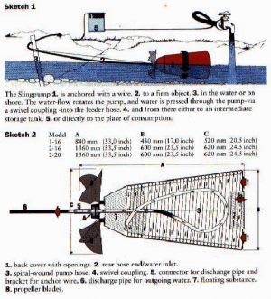
I plan to use a 216 liter (90x65cm) bucket in the shape of a truncated cone. The inside of the bucket will be lined with an irrigation hose (16 or 12 mm ID). The end of this hose gets connected to a rotary joint that sits at the bottom center of the bucket. A propeller is mounted to the same side to keep the bucket rotating. That's basically it.

Thanks a lot for your help.
 
Replies continue below

Recommended for you

Drawing?

Picture?

Link to a site which explains your design?

What powers this thing?

What sort of lift and flowrate are you looking for?

Remember - More details = better answers
Also: If you get a response it's polite to respond to it.
 
Oh sorry, I thought that the question was so basic that everyone in a pump forum could only yawn about it.

Ok, a sling pump is kind of a modified Archimedes screw that is driven by river flow. This is not a great picture but probably enough to get the twist.
Sling_Pump_Diagram_hyxufd.jpg


Otherwise, there is this video...

Lift, ideally around 15m. Flowrate, not so important. If I only get 1 m3 per day that is fine, everything more would be great.
 
Seems you answered your own question, ask the people who posted the YouTube link
 
The volume and pressure out of the pump is unaffected by the volume of the hose leading out; only the height above the pump is a factor.

The bigger problem is there is no formula for buckets and handmade propellers to predict the amount of torque that will be applied to the water to force it up the cone as the bucket turns. That is something you will need to experiment with.

The video includes a key element - trapped air. Without air gaps there can be no differential weight on the pump and without that differential water won't be pumped. That's why this pump cannot be fully submerged and still work and why they mention the styrofoam.

If it was stopped from rotating and pressure applied to the outlet, it would look like a series of u-tubes distributing the pressure over each of the u's. A few inches of difference at each turn times the number of turns is the total height. The lift volume depends on the propeller, but the turn rate cannot be particularly fast. In an open stream trying to increase the propeller rate will force water to bypass the propeller from too high a resistance.

In short, you'll have to build one and see if it works.

 
Thanks 3DDave, that is useful. I don't need an exact measure, I only need to understand which are the determining factors for head pressure, as I don't want to achieve maximum lift, just a suitable one.
So, from what you say, it exclusively depends on the number of coils? Doesn't the diameter of the coiled hose play a role? From what I found online, pumps with higher lift seem to have smaller diameter hoses but I don't know if that is just in order to get more coils per cone length or if the diameter plays a direct role.
Is there some type of inverse correlation between volume and pressure? As the energy delivered from the river is constant, I would imagine that you can't have the same pressure with large volumes as with small ones. But this is just guesswork.

And would the diameter of the bucket make a difference? I.e. does having a coil diameter of 1m instead of 60cm make a difference with respect to pressure?

I will definitely build one but would like to at least have enough information to buy the approximately right materials.
 
Tasss,

This type of "pump" is not common in anything other than the very simple pump world.

It also seems t be called a "river pump".

These sources ar interesting

The second shows one which is more like a water wheel which might be better.

But yes, follow the energy.
The greater the flow the lower the head and vice versa.

As you follow the loops around an ever decreasing circle it looks like each turn generates a small increase in air pressure. Your limit is the power you can get from the river via a small propellor or water wheel.

These look quite good but like all these simple machines are limited in scale and any debris in the river (branches, animals etc) will kill your machine, not to mention variance in flow, floods, silt etc.

There are many simple machines which could do the same work, but each location is different.

Good luck and let us know how you get on.

Remember - More details = better answers
Also: If you get a response it's polite to respond to it.
 
Thanks, LittleInch.

Yes, it is very basic, which makes it suitable for many developing country contexts where people just try to get by and have little or nothing to invest. I had assumed that engineers start learning about their field with a certain historical chronology, but then I realized also that even if that was true, I also don't remember all the stuff that was taught in the first semesters of Uni. So well, my false assumption.

Thanks for the links, I had seen this but it is very unspecific, lumping head and discharge together, which is exactly what I would like to separate.

"As you follow the loops around an ever decreasing circle it looks like each turn generates a small increase in air pressure. Your limit is the power you can get from the river via a small propellor or water wheel." Thank you! The "ever-decreasing" explanation is key and I was not exactly sure if that was a crucial element of the system. So this is a very helpful remark. I had assumed the pressure came mainly from the air being pushed along and then heading upwards pushing the water in front of the bubble and creating some suction effect in its rear. But your explanation makes more sense. And it also means that larger coils allow for bigger overall differential pressure, so coil diameter does matter.

So, to maximize head I should aim for
- a small coil pipe ID
- a large coil diameter
- a large number of coils
- an efficient prop to generate enough and constant torque

Thanks so much to all of you. That was really helpful.
 
One study problem is that this pump is not a historical one. It required the development of a thin wall elastic tube of great length and a buoyant material that will not become water-logged to allow it to float and a leak-free low-friction rotary coupler. It literally could not have been economically developed before 1900, possibly as late as 1950 or whenever expanded bead polystyrene became cheap.

Typical engineering study focuses on analysis techniques and not abandoned or marginal history. A modern EE student probably spends 0 hours understanding magnetic bubble memory or even magnetic core memory, as interesting as they might be; they are dead ends. They should study ferrites and hysteresis, but not as memory storage devices.

Sequential (wheel or chain) bucket pumps are generally historical, as are what I would call dip pumps, where a counterbalanced bucket is lowered to fill it, lifted and dumped into a trough/canal. I do however, enjoy watching what wheel bucket excavators can do.

The smaller the tube ID the less torque it should take to operate it, though the greater the friction losses will be. A large diameter will also increase the operating torque. The larger the number of coils the greater the friction losses will be, but the higher the pressure it can supply. Getting the low-torque pressure holding rotary coupler will be the biggest challenge.
 
All dependent of sufficient river flow/speed - and if this is available a hydraulic ram-pump is probably a better less complicated alternative. Also worth looking at a water wheel driven piston pump.

It is a capital mistake to theorise before one has data. Insensibly one begins to twist facts to suit theories, instead of theories to suit facts. (Sherlock Holmes - A Scandal in Bohemia.)
 
3DDave, fair points. The floating material would have been less of a problem in olden times, they used air filled animal bladders or reed gras etc,, but the smooth tube with constant diameter would probably have been a challenge. And as you say, the coupler. That's still a challenge today in many places. But I believe I can find those in Chinese markets, they are everywhere and have surprising stuff on offer especially if quality is less of a concern.
As to your final remarks, I will need to find a suitable balance between trade-offs. But understanding now the relevant variables, I trust I will manage. Thanks!

Artisi, yeah, river flow is alright. A ram pump is no option because I have no height differential to work with. We are talking about the Mekong River, it goes fast at places for a large stream but it has little slope. A water wheel is in theory an option but requires significantly more investment and engineering and anchoring is a headache. With theft being a major problem, I want to keep it simple and potentially mobile. But thanks for the ideas.
 
This is a slightly different version
Or I'm guessing here that the more loops you have the greater the pressure / head, but then you might need bigger paddles or a faster flowing river.

"water wheel" or "Spiral Pump" phrases get you more information.

Haven't read all of this, but might have some more data for you
Remember - More details = better answers
Also: If you get a response it's polite to respond to it.
 
Thanks! The videos I had seen already but the document is interesting, as they did some real testing and put the data up. Great find, thanks a lot. I guess this will at least give me an indication for the first prototype. Thanks heaps fo the effort.
 
No problem.

Just be sure to tell us how it goes or send a link to a video.

LI

Remember - More details = better answers
Also: If you get a response it's polite to respond to it.
 
Will try, but it may take a while.
 
Tasss; You may not want to overlook ram pumps. Technically they don't need fall to do their job they need only a constrained moving water stream. They get their lifting action from water hammer which can happen with any water flow constrained by a pipe. In your case you'd want the style with straight-thru flow with the outlet hole straight out the end. If the Mekong moves at a face walk you probably would have enough to pull it off.

Keith Cress
kcress -
 
Status
Not open for further replies.

Part and Inventory Search

Sponsor