Eng-Tips is the largest engineering community on the Internet

Intelligent Work Forums for Engineering Professionals

Slip Critical Connection

Status
Not open for further replies.

StructuralAddict

Civil/Environmental
Jul 19, 2016
103
0
0
CA
Hi,

The bolt slip resistance in slip-critical connections is Rn/Ω = [μ Du hf Tb ns /Ω] per Eq. J3-4 of AISC 360-16.

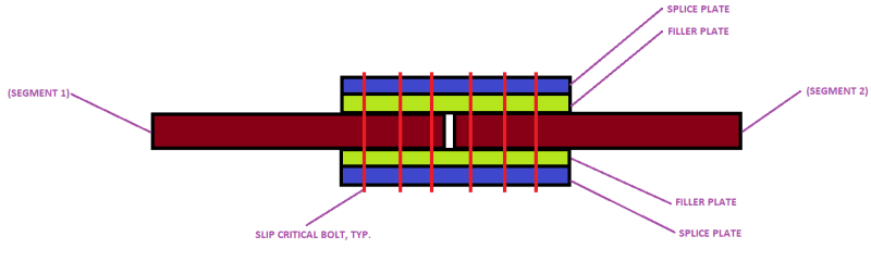
For the splice shown below:
(1) What should I use for (hf)? Is there one filler between the connected parts (hf = 1.0)? Or are there two fillers between the connected parts (hf = 0.85)? Please refer also to Figure C-J3.3 in the Commentary of AISC 360-16 that shows how they defined single vs multiple filler plates.

(2) The filler plates have long-slotted holes, so this will be taken into account by adjusting the Ω factor to become 2.14 per Eq. J3-4. Just wanted to confirm this?

Thanks.

SPLICE_wikrya.png
 
Replies continue below

Recommended for you

1) From the commentary figure this would be a single filler. But, as sketched, you wouldn't need the fillers. Fillers should only be needed on one of the segments.

2) I'm sure the slot would need to be in the splice plate to need the higher Ω. You could still use the 2.14 to be conservative.
 
Fillers are only needed if the flanges are different thicknesses, and I've never designed, or even seen a filler plate with slots.

I can't help with the equation. AASHTO has an equation with completely different variables.
 
Bridge Smith said:
Fillers are only needed if the flanges are different thicknesses, and I've never designed, or even seen a filler plate with slots.

"Finger Shims" are sometimes used in bolted end plate moment connections to make up any gaps between the end of the plate and the column. It just helps with erection. Here is a picture from the AISC design guide on the subject. I don't see any reason why this sort of thing wouldn't work in other situations as well. I'd have to read through the literature to see if the use of these types of shims changes the design at all. My impression is that it does NOT.

finger_shims_ar3t6n.png
 
Please refer to the sketch below on a case where the filler plate with big holes is used. Sometimes, the fillers are used with big holes (assumed as slotted holes) to reinforce existing built-up girders. This is done by adding a filler plate having a thickness exceeding the rivet head thickness and having hole diameters exceeding the rivet head diameter. Then, the reinforcing plate is placed on top of the filler plate and then the rivets are drilled one by one and replaced with high-strength bolts. The filler plates can be interrupted but the reinforcing plate must remain continuous.

For slip-critical bolted connections, I wonder if the filler plates should be considered when determining the Ω value in this equation Rn/Ω = [μ Du hf Tb ns /Ω] per Eq. J3-4 of AISC 360-16? And how many filler plates should be considered in the sketch below (i.e. what value of hf should we use? 1 or 0.85?)

splice_3_azij3u.png
 
StructuralAddict said:
Please refer to the sketch below on a case where the filler plate with big holes is used.

I didn't know that was even done. Is that what you're doing? Seems like a lot of work, as opposed to just shoring the beam (if required), drilling out all the rivets, and installing new plates with bolts.
 
Yes, this is performed when shoring the girders is not feasible in order not to block the traffic under the bridge. The girder is reinforced while a portion of the bridge remains operational.
 
Unless this was going to be done with traffic on the bridge, I would think in nearly all cases, the splice could be replaced half at a time. You'd cut the existing outer splice plate along the centerline of the girder, drill out the rivets on one half of the splice on both sides of the splice, replace the inner splice plate and half of the outer plate with a new inner plate and half-width outer splice plate, install and tension the bolts, and then repeat for the other half of the splice.
 
Status
Not open for further replies.
Back
Top