Continue to Site

Eng-Tips is the largest engineering community on the Internet

Intelligent Work Forums for Engineering Professionals

  • Congratulations KootK on being selected by the Eng-Tips community for having the most helpful posts in the forums last week. Way to Go!

Slot depth up to cylinder centre

Status
Not open for further replies.

Sa-Ro

Industrial
Jul 15, 2019
273
Hi

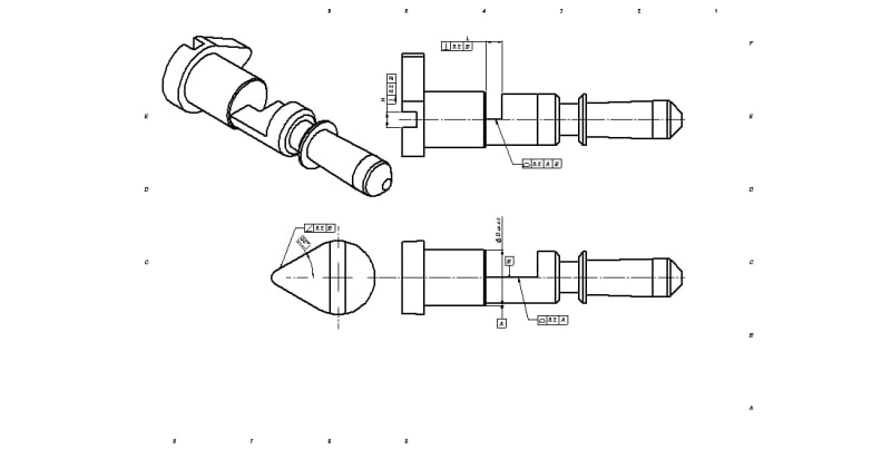
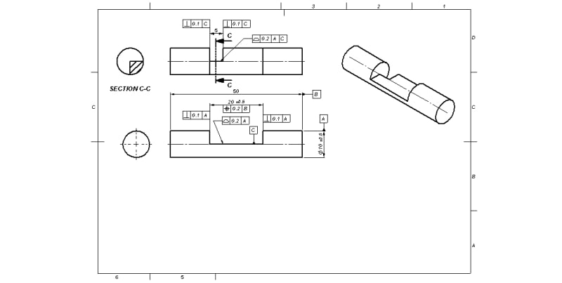
Refer the image.

Slot_with_cylinder_eghfo8.jpg


My requirements are:

1) 20 width slot shall be symmetrical to 50 length.

2) Depth of the 20 slot shall be within 0.2 symmetrical from dia 10 center line.

3) 5 width slot shall be perpendicular to datum C.

4) Depth of the 5 slot shall be within 0.2 symmetrical from dia 10 center line.

How to represent the GD&T for depth of slot wrt cylinder center line.

Shall I place profile of surface wrt datum A on flat face?

Thank you
 
Replies continue below

Recommended for you

Interesting set of requirements.
Is it driven by the function of the part, or did someone just felt like it "shall" be this way? If function is important, describing it might help you get better answers on how to do the tolerancing.
 
It is already aligned as required to the center line. There isn't a need for the additional perpendicularity on the left end to datum feature C. It's the same surface as in the view that establishes datum feature C - the left end surface that is perpendicular to datum feature A.
 
Hi

@Burunduk

This is our actual component.

Manual_override_xhkouz.jpg


This is a manual override component. You can see this component in a solenoid valve assembly.

Entire diametrical surfaces are guided into a stepped bore.

It will be pushed from screw driver slot and turn 90 degree clock wise to lock by metal plate.

A metal plate (thickness less than "L") is placed on datum B with slight clearance from center line.

It is used to actuate another mechanical component at front end taper.

@3DDave
Do you mean side faces of 20 width slot?

Size tolerance of this width is +/-0.5. If I am not restricting the perpendicularity of this side faces with in 0.1, these faces are allowed to vary from 19.5 to 20.5.

Kindly correct me, if I am wrong.

Thank you.

 
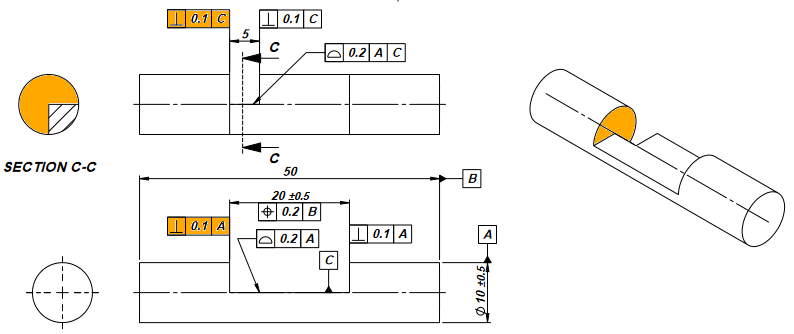
You applied two perpendicularity tolerances to the same surface in the initial example.

You have a different scheme in your actual part.
 
@3DDAve

Any hand sketch will be highly helpful for me to under stand.

Thank you.
 
sa-ro_example_dara61.png


The two perpendicularity tolerances are applied to the same surface, all marked in orange.

There is no rule against it, but I doubt there is any reason to do it.
 
@3DDave

Thanks for this wonderful diagrams.

There is no reason for mentioned at two places.

I thought, perp FCF placed in lower view is applicable for top half (first two quadrant) of the surface.

So that I placed second perp FCF on top view which will cover the third quadrant.

Thank you
 
Yes, the surface profile would establish tolerance zones for the bottoms of the slots, that are aligned to the datum axis.

First thing you should do is to consider how this component is held and constrained in the assembly and choose the primary, secondary, and tertiary datum references accordingly - you mentioned that the diameters mate with a stepped shaft - by what type of fit?
The tolerance on the ⌀10 mm diameter in your initial figure was ±0.5. In the latter figure it is 10 times smaller, however it still doesn't look like a candidate for a primary cylindrical datum feature unless the bore it mates to is a chuck-like adjustable device.
After the decision on the datum scheme according to the way this part is constrained, apply the required orientation and location tolerances according to the chosen datum scheme to the features which mate with the metal plate and any other component that depends on this part for its constraints: position with orientation refinements, if required, to slots and other features of size. Profile with orientation refinements, if needed, to surfaces of features without size such as the bottoms of the slots.
 
@ Burunduk

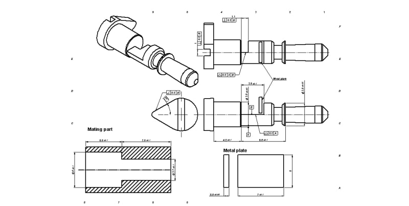
Refer the below image for mating components

314065-01_psvav6.jpg


Since dia 3.8 is guiding the component I prefer to set it as datum A. Mating part is not a clamping type. It is a fixed bore where the manual override can move front and back, rotate along the axis.

Thank you


Status
Not open for further replies.

Part and Inventory Search

Sponsor