Continue to Site

Eng-Tips is the largest engineering community on the Internet

Intelligent Work Forums for Engineering Professionals

  • Congratulations KootK on being selected by the Eng-Tips community for having the most helpful posts in the forums last week. Way to Go!

Slotted HSS End Connections - eccentricity 8

Status
Not open for further replies.

dik

Structural
Apr 13, 2001
25,677
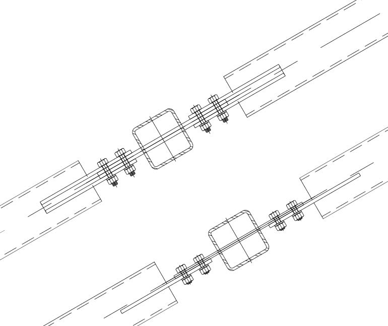
How do other engineers deal with the slight eccentricity caused by the slotted end connection to the gusset plate due to the thickness of the connecting plates. I generally offset the slotted plate and the gusset plate so that the face of the plates falls on the centreline of the HSS to minimise the moment. I neglect this when I design the connections. What do other engineers do? Are there any references? [ponder]

Rather than think climate change and the corona virus as science, think of it as the wrath of God. Do you feel any better?

-Dik
 
Replies continue below

Recommended for you

"Can you elaborate on that? Do they have something special? or is it P/A and M/Z..."

That's essentially it. P=Axial load; A=controlling axial limit state; M_weak_axis=e*P, where e=0.5*(t_gusset+t_conx_pl); Z= weak axis plastic section modulus;
Hasty incorrect answer. The interaction equation from ChH has the definitions.
 
Thanks Hopi, for the 'heads up'... I've been doing it wrong for 50 years... I think I've always used plates; I don't think I've ever used a channel. ]The reason this has come up is that some of the bracing forces are large and in compression. I also want bolted connections, not field welded... I'm pretty comfortable with what I've decided. That link provided by Hokie (one I already had) but was faster than trying to find it myself. I had done an SMath program for it a while back.


and checking would be based on the Whitmore dimension?

Rather than think climate change and the corona virus as science, think of it as the wrath of God. Do you feel any better?

-Dik
 
Thanks 80%... the problem is the compression loads in the bracing are higher than I normally encounter, so just want to make sure my ducks are in a row. With tension members, I just let them yield a bit... then they behave elastically.

Rather than think climate change and the corona virus as science, think of it as the wrath of God. Do you feel any better?

-Dik
 
human909 said:
For very large loads my alternative is sandwich plate either on the strut or as 2 loose additional plates. This avoids eccentricity, avoid extra welding plus you get bonus double shear in your bolts.

That does sound marvelous. Does that make for a fillet weld access problem for one of the plates and necessitate CJP?
 
The sandwich plates are best loose, fully bolted. I don't like just making the single plates thicker to solve an eccentricity issue, as that increases eccentricity, so you are chasing your tail.

For me, it is bolted sandwich plates or stiffeners.
 
Ah... it's two plates sandwiching both the gusset and the slotted plate. I though it was a double gusset. Thanks.

It's good to a have you back in the technical fora hokie66. I'll soak it up while it lasts.
 

The sandwich plates are welded to the HSS bracing members...Something like... The through plate in the HSS would likely be twice the thickness of the 'sandwich plates'. Fixed...

Clipboard01_j256c3.jpg


Rather than think climate change and the corona virus as science, think of it as the wrath of God. Do you feel any better?

-Dik
 
hokkie66 said:
The sandwich plates are best loose, fully bolted. I don't like just making the single plates thicker to solve an eccentricity issue, as that increases eccentricity, so you are chasing your tail.

For me, it is bolted sandwich plates or stiffeners.
Fair enough as I elaborate below I do think your approach is structurally more elegant. Though from a cost perspective it is more expensive. Regarding chasing your own tail, that is true but it is a convergent behaviour so thicker plates do result in sufficiently strong connections. I've happily used 32mm plates to get some connections to work.

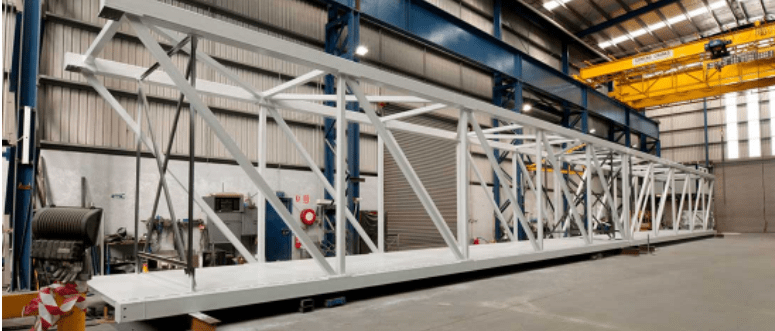
The biggest connection I've done like was years ago before I had finished my degree. The designing engineer provided a connection that was single 20mm plates for an extremely large load. It just looked wrong, and I'm glad I intervened as it was a high load critical connection on a compression cord of a heavily loaded long span truss. I as a non engineer upsised the connection to 40mm with two 20mm sandwiched it together. Really a end plate connection would have been better.
6_r7w4fg.png


kootk said:
That does sound marvelous. Does that make for a fillet weld access problem for one of the plates and necessitate CJP?

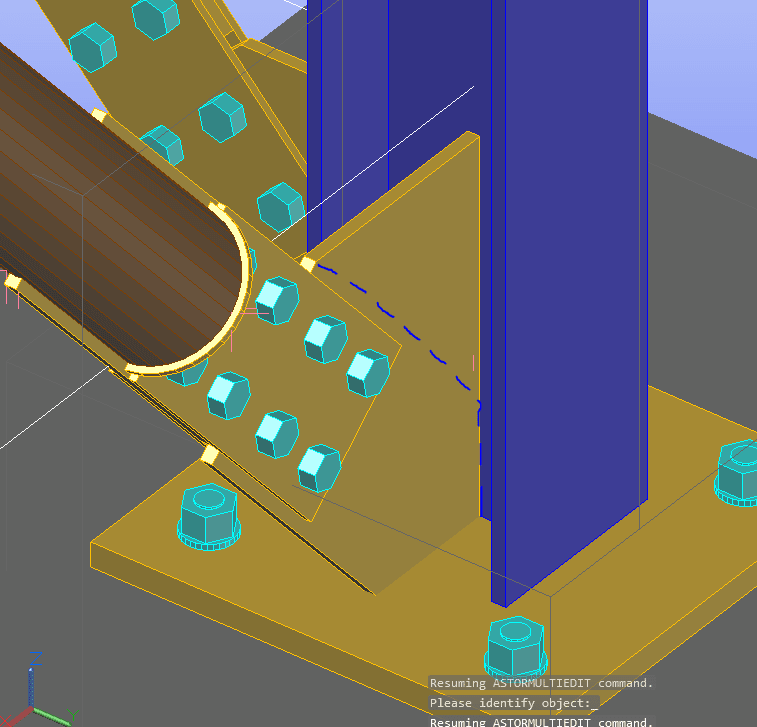
No, the twin plates if used are on the hollow section as drawn but dik normally with a spacer plate in-between, that is how I've done it in the past. Though what I was actually meaning in my above comment was a single plate on each with 2 loose plates sandwiching them I think this was hokkie's prefernce. I have no distinct preference with either option. They are both more fiddly than just using single thick plates but they are both structurally more elegant.
Example grabbed from online:
Capture_vj6jr8.png


I've observed plenty of WRONG ways to do these connections continuing to be built. As the many comments here suggest there are numerous preferred 'right' ways to do it. I just wish more engineers in my country were aware of this issue and applied one of these 'right' ways.
 
human909,

No excuse these days for not knowing, as the issue has been well defined for many years.
 
KootK,

I lurk, but tend to find less that I can assist with.
 
Having seen a real life failure attributed to this many years ago in Australia which kicked off the investigations that lead to the design procedures being developed in NZ to account for this. It's not something you want to eyeball and ignore. The costs associated with investigating the failure and rectifying it were significant for all parties involved. The designer did not even look at any eccentricity effects in this case, didn't help either that the contractor used G250 plate instead of G350 required (only discovered after investigating coupons from the failed plates).

The NZ design approach limits eccentric cleats to elastic seismic design, and then offers a moment magnifier to account for the second order effects to make some allowances for the additional moment due to the inherent 'sway' effects. Just taking the moment due to eccentricity in the centrelines of plates may not be sufficient to guarantee adequate performance. Obviously, this is worse for longer cleats.

The best approach is one of avoiding these types of connections, especially with higher loads or dynamic loads. Try to make things concentric, or stiffen longer cleats.

 
I ran in to this issue when reviewing a project a couple of years ago. The original designer had ignored eccentricities. Some of the gusset plates were very long as they were picking up 2 incoming members that were at shallow angles to each other. The reduction in capacity of the connection when allowing for the eccentricity can be very significant, even for compact connection details. This paper discusses the design approach proposed by the SCI in the UK to account for the eccentricity (likely similar to the other papers others have provided links to). Previous guidance from the SCI in their connection design manuals had stated that eccentricities could be ignored in this type of connection, this only changed in 2014! (likely why the original designer had ignored it, as this is what they had always done based on the old guidance). Note, the eccentricity will also cause additional bending in the bracing members that needs to be accounted for in the member design.
 
My meager contribution:
My office's standard for tube bracing connection is a slotted tube with a hole for an erection bolt, and then field weld the tube directly to the gusset.

For a particular client, they wanted no field welding. So, I used RISA Connection to assist with the design of these connections. Obviously I wanted the gusset to stay centered on the beam and column, and the knife plate to be centered on the tube. RISA Conn will allows the user to force the knife plate to take ALL of the moment(s) due to the eccentricities. This led to designs that were 3/4" gusset with a 1-1/4" knife plate - certainly not my idea of optimum or efficient, but, in my opinion, pretty robust.

Related: I'm surprised that Josh Plum hasn't jumped in to this discussion. I thought he had done a bunch (most?) of the analysis and checks for RISA Conn.

 
dik said:
How do other engineers deal with the slight eccentricity caused by the slotted end connection to the gusset plate due to the thickness of the connecting plates. I generally offset the slotted plate and the gusset plate so that the face of the plates falls on the centreline of the HSS to minimise the moment. I neglect this when I design the connections. What do other engineers do? Are there any references?

Hi dik,

AISC Design Guide 24 has a quite conservative design procedure for this condition, where the bending moment due to the lap eccentricity is evenly distributed between the connection plate and the gusset plate. I think it's a reasonable assumption as long as both plates have similar bending stiffness.

I also think that it is not appropriate to assume that the knife plate takes all the moment. Even if the gusset plate is centered with the brace, it will still attract part of the moment due to its own bending stiffness. The axial force in the brace will be transferred from one plate to the other and the moment created by the lap eccentricity will be distributed in proportion to the relative stiffness between the plates, regardless of the relative location between the plates and the brace centerline.

 
Thanks pro... I'll take a look...

agent and pat... For tension members I generally ignore the eccentricities(except at the actual connection)... something will yield the first time it's loaded fully, then it will behave elastically; I don't have any concerns. The latest project for me to design connections for was for HSS x-bracing where the compression forces are equal to the tension forces and some of them with a magnitude of 150K (I don't know if this was an oversight by the EOR, but don't want to go there). With large compression loads, I generally become a little more concerned. I've seen recent photos of bridge gusset plates buckling. I've checked it for the plastic buckling of Hokie's reference, the elastic stresses as well as the Whitmore compression for gussets, and it works fine. I'll see what DG24 has to say, and include it in my SMath program (it's only 12 pages, so far.)

I've sent an RFI to the EOR to confirm that I can design the connections for the eccentricity. I often do work where I don't have a full deck and have to stipulate my assumptions to be confirmed. I don't know if the EOR wants eccentric connections. I also don't know if the bracing has to be slip critical (I generally design for that, but with loads 1/3 of those stipulated. Sometimes it's not always req'd).

Rather than think climate change and the corona virus as science, think of it as the wrath of God. Do you feel any better?

-Dik
 
Thanks pat... that's quite a reference. I just flipped through it.

Rather than think climate change and the corona virus as science, think of it as the wrath of God. Do you feel any better?

-Dik
 

My current work is designing connections for metal fabricators; they are, generally, looking at the least cost. I'm really not a big advocate of field welding for 'real' loads, and would prefer all significant welds to be 'shop'. I've almost finished by SMath program (even if it is Russian, I still like and use it); I'll post it later...

Rather than think climate change and the corona virus as science, think of it as the wrath of God. Do you feel any better?

-Dik
 
Yeah dik, I ignore for tension as well on the basis that even if there is some localised inelastic bending occurring as things 'straighten out' it is still globally stable. The bending just redistributes (or at least tries to) to a pure tension state in my mind.

If things are yielding in tension it makes compression stability even worse as things unlikely to be perfectly aligned on the reverse cycles. This I'd imagine increases the propensity for a lateral sway action effect.

I believe the NZ approach proportions the moment based on the member and gusset stiffnesses, so you get the lions share going into the gusset as I remember it as the sway behaviour kicks in (as member generally stiffer by orders of magnitude).

 
Thanks agent... It's cross-bracing, so I suspect maybe 60% of the load may be in compression... dunno... but the connection will take the full load. We're not in a seismic area, so I'm not concerned about shakedown (caused by internal stresses) or plastification of the connection. An extra 1/8" on gussets, costs almost nothing... I'll run the design and see where the weaknesses are... and go from there.

That's what I like about SMath programs... I can change parameters and only print the output and can append them to the earlier output. Slikker than doggie poop...

Rather than think climate change and the corona virus as science, think of it as the wrath of God. Do you feel any better?

-Dik
 
Status
Not open for further replies.

Part and Inventory Search

Sponsor