Continue to Site

Eng-Tips is the largest engineering community on the Internet

Intelligent Work Forums for Engineering Professionals

  • Congratulations pierreick on being selected by the Eng-Tips community for having the most helpful posts in the forums last week. Way to Go!

Small Parallelogram Parking Structure Feasible in Precast?

Status
Not open for further replies.

KootK

Structural
Oct 16, 2001
18,405
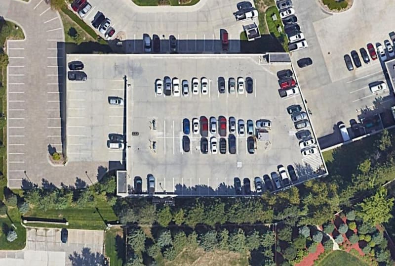
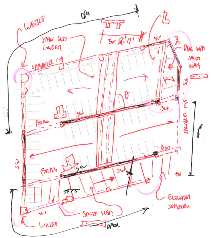
I'm doing a feasibility study on a small parking garage:

- 200' x 200'-ish.
- Two levels above grade.
- A rectangle if possible, a parallelogram if not.
- Coastal, high seismic (I'm not worried about this part).
- Precast TT and spandrel if the numbers make sense, mildly reinforced CIP if not.

My questions, which I'd like to have considered separately:

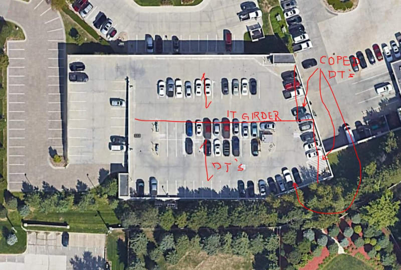
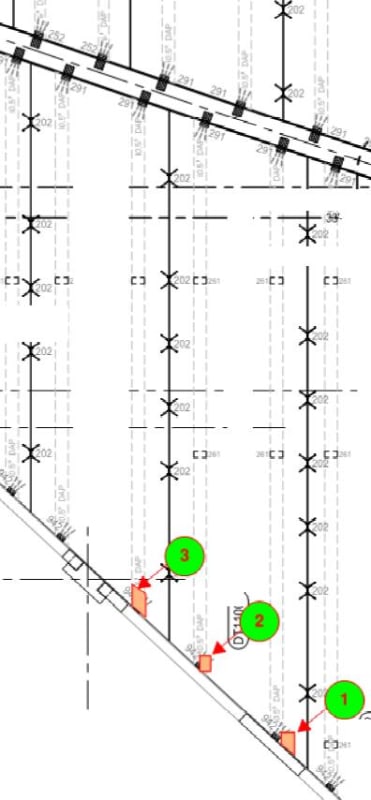
1) How viable is a parallel shaped parking structure like this in precast? I've had the good fortune to only EOR these things a sexy rectangles thus far. Can the ends be skew cut like I've shown? Got any better ideas for layout, especially at the top right? whatever I do will have to make sense for drainage.

2) How viable would a rectangular parking structure this small be in precast? In my home market, precast usually comes out on top for anything of any appreciable size. This one is pretty darn small however. At some point, I'd have to think that there would be so few precast pieces that the scales would tip in favor of CIP.

c01_gsnsoj.png
 
Replies continue below

Recommended for you

Parallelogram shaped DT's can be cast but would require custom end separators which are typically made form steel and would drive the cost up given the small quantity to amortize the cost over.

The corner columns would require some thought and custom forming but they are typically not prestressed so that could be managed.

Seismic should not be a problem. I recently completed a 4-story all precast parking garage 180'x 116' in Oakland which had less shear wall than you are showing.
 
They did the Montreal olympic stadium in precast (...they really shouldn't have); if you have 'big pockets', this could be done... I'd likely do it in CIP...

-----*****-----
So strange to see the singularity approaching while the entire planet is rapidly turning into a hellscape. -John Coates

-Dik
 
KootK,
I did a auto-dealership service garage with a rooftop parking area that had a severe wedge shape on one end.
(see the attached arial image).
The left side was a ramp (on EPS Foam Fill) going up to the upper deck. All double tees supported by inverted "T" beams.
The left side, as you can see, was a nifty rectangle shape but the right side had an angular end. They simply coped off the DT's as required and
provided support ledges along that eastern (Right side) wall.

We did take the time to visit with a precaster ahead of time to verify that at least one precaster could handle it.

Lexus_Garage_id7v6m.jpg
 
Here's a more accurate framing plan.
The area with the doubled DT's is due to us shallowing up the DT's because there was a mezzanine below that area and we needed all the headroom we could muster.

Garage_3_tj16po.jpg
 
I'd line up the planks like what JAE is showing instead of making each precast piece a parallelogram.

Screenshot_2023-11-28_151542_al9bvg.png


That's one I did. Not a parking structure, but the top area had slanted planks. Zero issues with the fabrication.
 
Thank you gentlemen.

JAE said:
They simply coped off the DT's as required and provided support ledges along that eastern (Right side) wall.

"coped" = blocked off the ends of the TT forms somehow, right? Your skew ended TT weren't saw cut after casting etc?

Was there anything special about the way the TT bearing seat was constructed at the coped ends?
 
JAE,

Is there a bearing angle for the double-tee slab at the skewed angle?
 
"coped" = blocked off the ends of the TT forms somehow, right?
Yes - the ends of the TT were at an angle

Your skew ended TT weren't saw cut after casting etc?
Not sawcut - formed with the skew.

Was there anything special about the way the TT bearing seat was constructed at the coped ends?
The seats were simple concrete (cast) corbels as part of the wall panels.


If you can build something like this as panels and not have to do the skewed bar arrangements and stuff in the field it's going to be a lot more straightforward.

If you have to cast it in place be really careful with the skewed reinforcement and shear pathways. If you can frame it as rectangles or rectangles plus triangles you'll make your life more straightforward. If not, just build in time for a bit of extra screwing around with math and details.

1. If your bar isn't at right angles you'll have to be really aware of what you're doing at every design step because there are a lot of assumptions built in to design methods, and presumably all of your spreadsheets and software have this assumption in them as well.

2. If your bars are at right angles, you have the opposite problem of your spans being weird compared to the bar orientations and needing to adjust for that. Skewed panels also have large Mxy effects that you need to keep an eye on in case you're doing two way design in software that doesn't deal with that well.

You're also going to have guys implementing it wrong in the field.
 
JAE said:
The seats were simple concrete (cast) corbels as part of the wall panels.

The wall side of the connection I've got a bead on. What I'm wondering about is the TT side of it. You know, there's usually a bearing plate / DBA setup in there, sometimes with a very small dap of sorts. Maybe some HWS. Still got those? Are the plates still square or were they cut at an angle to suit the skew on the TT end? Perhaps this is more detail than you got into as the EOR. I did some hard time as a part time precast engineer so I'm a bit sensitive to the details.
 
You know, there's usually a bearing plate / DBA setup in there, sometimes with a very small dap of sorts. Maybe some HWS. Still got those?
Most didn't have daps in the DT's. Only where we were trying to keep headroom high we dapped the DT's and I think used steel angle bearings.
Otherwise simple embed plates on the bottom of the DT stems to allow a welded connection to the corbel bearing plate (embedded in the top of the corbel).

Are the plates still square or were they cut at an angle to suit the skew on the TT end?
I'm not sure whether square-to-the-world or skewed embed plates - can't recall and the shop drawings we have appear to show it.

Perhaps this is more detail than you got into as the EOR
Yes - we didn't dictate those kinds of things.


OK - so I guess there were conditions where they dapped the DT's more often than I recalled. Here's a couple of generic connections they used.

DT_Connection_1_ge04or.jpg

DT_Connection_3_ai8drq.jpg

DT_Connection_2_rh1ysb.jpg
 
It seems like others have covered the issues with skewed ends fairly well, and what I've seen would support what's already been stated on that subject.

I would just add that what we've seen in cost comparisons is that proximity to a precasting plant, and whether those nearby plants hve the forms for the sections you want to use, has a significant influence on the total costs. Transportation costs (for us at least) are a significant percentage of the overall costs.

Your job wouldn't small compared to the bridges we do, which are typically in the range of 50' x 100', and some smaller, and prestressed is regularly competitive with steel plate girder systems. Most of ours are decked bulb tee sections, though. We do some tri-deck (triple Tee) sections for spans under 60'.
 
I'd be tempted to keep the tees normal to the shear wall as best as possible to avoid the torsional stresses on the double tees (adjacent stems will have different deflections). For the triangular areas, frame with an L beam and flat slab wedge pieces.
 
Bearing plates can be either rectangular or odd shape.
Double tee stems do not have to follow skewed line of the flange,
which could reduce bearing area.
That's how typical or simple stem end form can be used.
Which one is better?
DT222_jjlnt0.jpg
 
Many times, a CIP option will cost less in actual construction cost but where it shines is in the macro cost. The Precast option saves months of time in the overall project and if the structure is completed earlier, it starts making the client his return on investment sooner.
This project went from footings to the pine tree on the final piece in 17 days.
 
 https://files.engineering.com/getfile.aspx?folder=e28f86f9-bd6a-47a7-a982-ca0e59be8c7e&file=Manila.png
I have seen many CIP concrete parking structures.
Their aesthetics is generally poor and inconsistent quality.
I wonder how the owner and architects react to many ugly looking details.
I know it depends on men's skill, but CIP concrete buildings like parking structures
may be too big to control their quality.
 
Why are you talking about cast in place concrete? CIP?
This is a question about precast concrete.

 
Status
Not open for further replies.

Part and Inventory Search

Sponsor