Eng-Tips is the largest engineering community on the Internet

Intelligent Work Forums for Engineering Professionals

Small Vertical Pressure Vessel Leg Support Design 5

Status
Not open for further replies.

Lega213

Chemical
Feb 24, 2017
12
0
0
GB
Hello all, I hope someone here can help me, forgive me if this is the wrong forum to post such a question. For background, I am a chemical engineer but I've been tasked with mechanically designing a reactor (pressure vessel) so I'm not too used to mechanical designs so I'm here for some assistance.

Information about my vessel:
Diameter = 1.5m
Ellipsoidal heads
Height = 2m
Design pressure ~ 25 bars

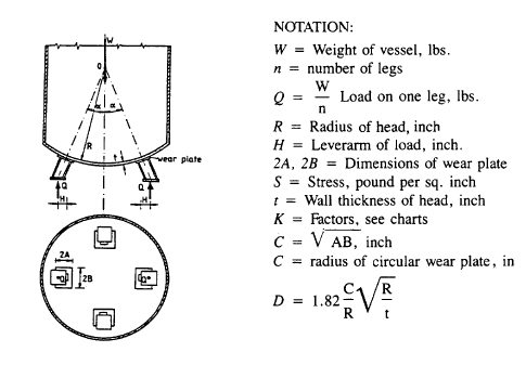
So as the title suggests, I'm trying to design some supports for this vessel. I'm using Pressure Vessel Handbook 10th Ed by Megyesy as reference. This is the image that they provide:

lllh_orgkv1.png


My questions are:
R = radius of head, is the centre of this circle the centre of the vessel?
Is S the tensile strength of the material?
H = leverarm of load, what does this mean?
A and B aren't clear, are they the dimensions of the base plates on the bottom of the leg support?

The end of the calculations don't seem to yield anything of importance.. just that the sum of the stresses do not exceed the stress value of the girth seam, does that mean the stress calculations are just used to check if leg support is viable?

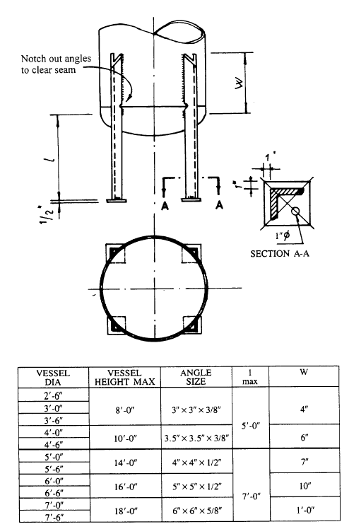
Finally, this table:

zz_iaylqo.png


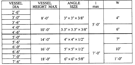
mentions an angle size, what angle is this, it doesn't even mention what angle...

If anyone can help I'll be very grateful.

Thanks
 
Replies continue below

Recommended for you

Actually ignore all of that, I've figured it out, angle size isn't the size of an angle, it's the dimensions of an ANGLE bracket lol.

What angle are they using in the first image though? and what R? My dish isn't spherical, it's ellipsoidal.
 
First, the information you describe contained in the PV Handbook is somewhat dated. These are older style PV legs. The legs will be too short for access to the bottom of the vesel

Second, there are many alternatives for vertical PV support. Acceptable designs include: angle legs, hollow tube supports, WF supports and complete support skirts. Search the internet and this forum !

Third, IMHO, the most important consideration for PV leg designs is to properly set the elevation for the bottom head from grade. You probably want to have some distance between the bottom head and grade to get access to such things as drain valves and level devices. 36 inches is typical .... could be more.

Fourth, study pictures of similar vessels. Some require reinforcing/ [poison) pads where there is a change in materials ( stainless steel to carbon)

Fifth: talk with your fabricator about his experience

Lastly, congratulate your MBA boss for assigning important and complex work to engineers with no experience in that field.

Remember, just before all MBAs receive their graduate degree they receive a tattoo that states " Anybody can do any job in any amount of time, you just have to count the manhours..."

MJCronin
Sr. Process Engineer
 
Hello, you can't just take some dimensions for legs from a book and expect it to work. You also need to provide a understandable design calculation in which you need to take into account earthquake , wind and other forces that impact your vessel.
Have you designed the rest of the vessel ? is everything else besides the legs ok?
Did you take into account loads acting on the process nozzles ? did you do a fatique calculation?
Please understand that design on pressure vessels is not about choosing different components from a book or catalog and magically making it working .
 
I will never accept a job if is out of my engineering qualification.
Try to change job and search a responsible company.

Regards
r6155
 
Gogu, I am not so naive, I was just trying to find some basis upon which I could do some research.

My vessel will be situated indoors and it is small, there are no seismic activities, there are no bending forces. As far as the actual vessel, yes I've taken all of that into account, I've designed the thickness of the vessel with my material to be able to withstand all loadings it is subjected to. These are somewhat preliminary calculations so I've used the equal area method to account for the nozzles/flanges. As far as the legs go, I've used the standards given in that book (angle size, L, W etc) and then I've done the required stress calculations. It turns out that because there's no wind or seismic activity, the standard length works fine. I will go ahead with this, and have it checked.
 
OK. Considering that England is still in the European Union you should read PED 2014/68/UE.
Oh,and by " loads acting on the process nozzles " you should read WRC 537 and WRC 297 . It has nothing to do with " equal area method to account for the nozzles/flanges ".
 
Thanks, I'll have a look. Do you know if it's okay to make the bottom part of the vessel, add the internals (baffles and coils) and then weld on the closure head?
 
Usually , for every vessel there is a manhole , about DN 600 . You need it in case something happens to the internals .
Some more questions :
- what design code are you using ( in EU there is 13445-3 and it is harmonized with PED 2014/68/EU )
- what is your design temperature ?
- what materials are you using ?
- what software are you using ?
- what kind of fluid is in your vessel ? do you have gas ?
 
it is your decision. But you said you have internals ( baffles and coils ) . All the vessels that i have designed have a manhole or, if a manhole can't be installed , have a body flange with a removable blind flange.
Something like this :
130-gal-precision-stainless-inc-stainless-steel-pressure-vessel-45625_nma2po.jpg

There will come a time when you will need acess to those coils.
 
"Usually , for every vessel there is a manhole , about DN 600 . You need it in case something happens to the internals" .
GoguGili, if you think this is true you are in a wrong way. Please read more about manhole (inspection opening).

Regards
r6155
 
r6155, i know that it is not required that a manhole of DN600 be put on every vessel. I have designed vessels with manholes , handholes and even headholes 😀 . My point is that there should be some sort of inspection opening. At some point in time you need to inspect the inside of the vessel.
Lega213: check asme section VIII, div. 1 , mandatory appendix 2
 
Gogu, your help has been much appreciated. I'm using PD 5500 instead. This is going to be a preliminary design, I'll my boss to get a mechanical engineering to check everything.
 
Be carefull, PD 5500 was withdrawn from the list of British Standards because it was not harmonized with the Europeran Pressure Equipment Directive PED (97/23/EC) , former PED 2014/68/EU. I don't know if in the latest revisions they made that harmonization.
And i didn't ask you if your vessel has gas for nothing : if your vessel goes into category 4 acc PED you will need the review of a Notify body ( mainly TUV or Loyd's ).
 
Status
Not open for further replies.
Back
Top