Hi,
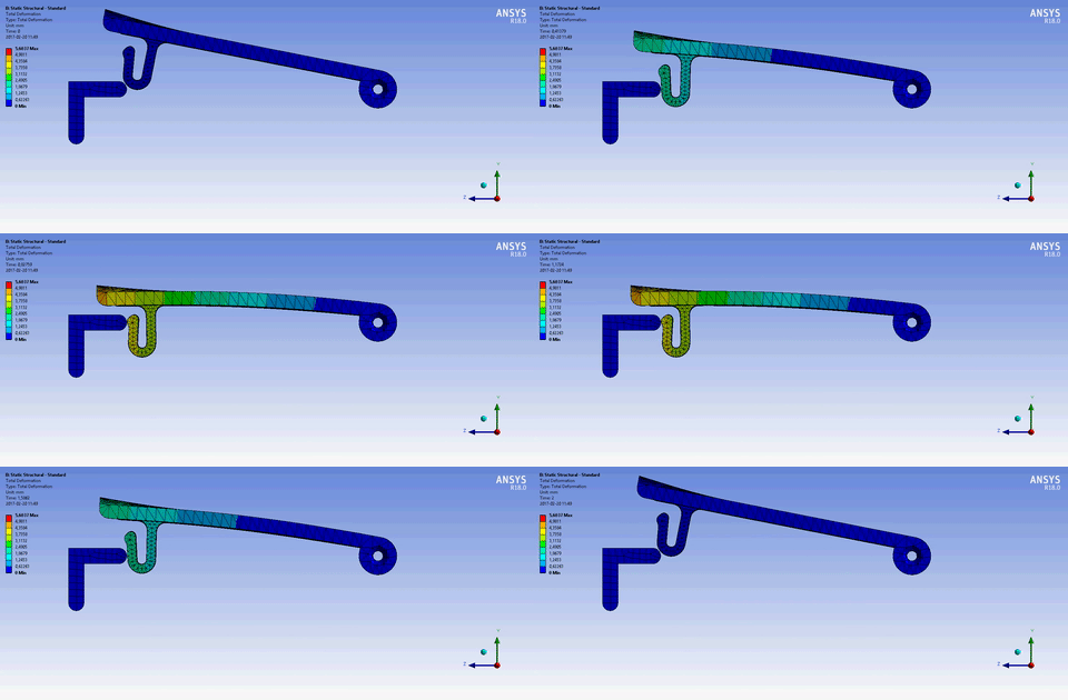
Currently I'm facing a problem of what I thought would be a rather simple setup with a snap fit design.
However I face some difficulties regarding the boundary conditions as I think it's important to get the snap to have a rotational displacement.
First of all: what is the proper way to do this? As for now I have a remote displacement on the edge of the part and just telling it to deform along the Y axis, which will be a linear deformation.

Secondly, (and this problem could be caused by my linear/bad remote displacement BC) when the part gets deformed the reaction force from the edge/snap tends to bend the upper surface. In reality this is where you will have your thumb and force the surface flat - this will ofcourse affect the stress/strain in the snap fit. How do I model a BC that mimics the support on the top part?
The surface still have to be able to deform downwards to the edge because of the movement, but be locked (stay straight) in when the snap wants to bend it. Can I add another cordinate system that follows the deformation somehow?

Thanks and please just ask if you dont understand my problem..
Currently I'm facing a problem of what I thought would be a rather simple setup with a snap fit design.
However I face some difficulties regarding the boundary conditions as I think it's important to get the snap to have a rotational displacement.
First of all: what is the proper way to do this? As for now I have a remote displacement on the edge of the part and just telling it to deform along the Y axis, which will be a linear deformation.

Secondly, (and this problem could be caused by my linear/bad remote displacement BC) when the part gets deformed the reaction force from the edge/snap tends to bend the upper surface. In reality this is where you will have your thumb and force the surface flat - this will ofcourse affect the stress/strain in the snap fit. How do I model a BC that mimics the support on the top part?
The surface still have to be able to deform downwards to the edge because of the movement, but be locked (stay straight) in when the snap wants to bend it. Can I add another cordinate system that follows the deformation somehow?

Thanks and please just ask if you dont understand my problem..
