Eng-Tips is the largest engineering community on the Internet

Intelligent Work Forums for Engineering Professionals

Soil Pressure Coefficient for Inverse Retaining Wall. 1

Status
Not open for further replies.

StrEng007

Structural
Aug 22, 2014
486
0
0
US
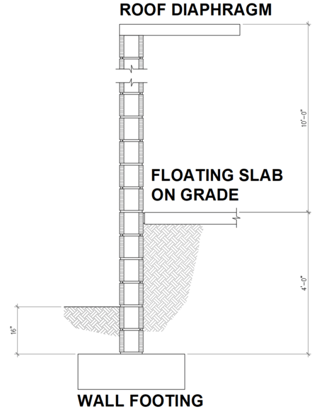
Normally retaining walls keep soil out of the structure. I have the inverse situation.

For the image shown below, when considering the overburden and surcharge loads inside the structure, would the lateral forces for the retained soil be determined with at-rest pressure Ko or active pressure Ka? Keep in mind, the overall wall height is 14ft tall and is required to satisfy L/360 = 0.466".

My overburden is developed from the 4ft of soil being retained.

My surcharge is developed from the 40PSF interior slab loading.
Note: I did not use the slab DL as surcharge, I let that reside within the 4ft of soil (in reality, for a 4" slab, that's roughly 50 PSF[sub][/sub])

Screenshot_2024-08-12_102016_ktbyzr.png
 
Replies continue below

Recommended for you

With the top restrained I would tend to design using the at-rest pressure, however there is a rational approach to use active pressure as it usually does not take a whole lot of movement to mobilize.

Guide for estimated translation for active soil pressure from Bowles:


Screenshot_2024-08-12_105318_qevbmx.jpg
 
If I can't rationalize full active pressure I've used a pressure between at-rest and active for a wall design that had some tight design restrictions, the eng. judgement behind this is the recognition that the pressure reduces down from at-rest to active as the wall deflects, I have done a straight-line interaction from this figure, Bowles again, and the movement values above:


Screenshot_2024-08-12_111236_vs85pf.jpg
 
I would design for something more conservative than L/360. That much deflection would be unsightly and could cause slab settlement.
Why not epoxy some slab rebar into the wall to brace it?
 
If you pin the slab to the wall it is no longer floating freely, risking significant misperformance if it isn’t properly designed as a suspended slab supported by the wall. Example: ferrules tearing out of a concrete wall in a similar configuration to yours.

failedjoint_wqllcv.jpg
 
It’s only a brace point if you complete the load path for the reaction through friction between the SOG and subgrade. It’s also my opinion that you don’t get any friction resistance within the soil failure wedge.
 
Celt83 said:
It’s only a brace point if you complete the load path for the reaction through friction between the SOG and subgrade. It’s also my opinion that you don’t get any friction resistance within the soil failure wedge

I imagine the OP could pin the perp edges instead of relying on friction. That being said, it is only 4 ft, of backfill. That ain't much force to resist.
Has anyone actually ever seen a slab slide in the wild?
 
Ended up going back to heavy wall reinforcing and the overall design was governed by high wind load C&C (175MPH Exp C).
The wall was designed without the additional support from the slab.
 
something to consider may be a temporary condition where the lower portion of wall is constructed, backfill placed, and then the wall is built up to accept the roof. You could always mandate temporary bracing down to exterior grade prior to backfill and to remain until the roof diaphragm is complete.
 
Status
Not open for further replies.
Back
Top