Eng-Tips is the largest engineering community on the Internet

Intelligent Work Forums for Engineering Professionals

  • Congratulations waross on being selected by the Tek-Tips community for having the most helpful posts in the forums last week. Way to Go!

SolidWorks Input File 1

Status
Not open for further replies.

WARose

Structural
Mar 17, 2011
5,581
0
0
US
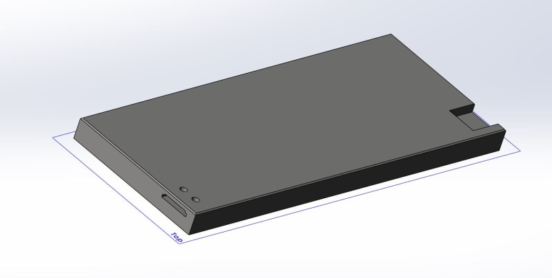
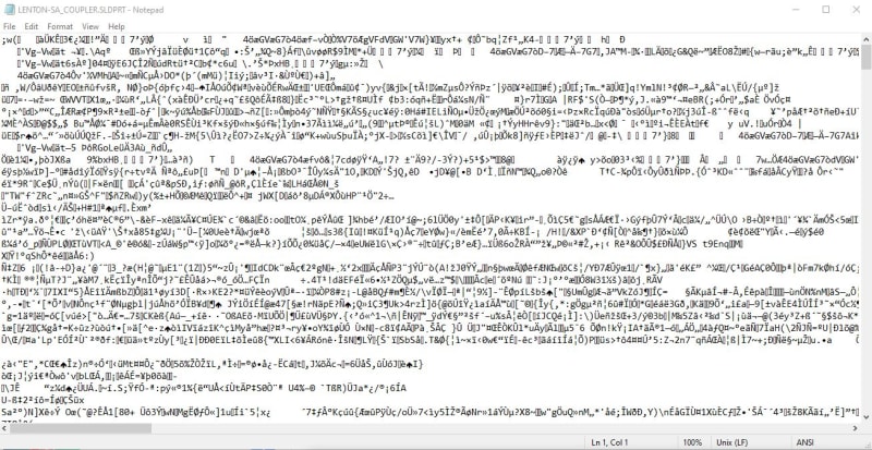
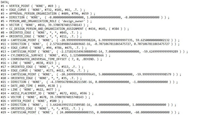
Does SolidWorks have a edit/input files that (in text format) gives joint coordinates, member incidences, etc. If so....could you give me a sample of what that looks like (i.e. the text)? A short (complete) file with loads and so forth would be great.

And by the way, what is the ballpark cost for SolidWorks?

No need (by the way) to remind me I have posted this in another forum. (Without reply for days.) I've reported that one so they will take it down.

Thanks in advance.
 
Replies continue below

Recommended for you

Are you trying to create different configurations of different parts or something else entirely? I would expect you could create a spreadsheet to drive the sketches of parts. Here is one video showing some methods how to extract data. Link
 
Are you trying to create different configurations of different parts or something else entirely?

Something else. I have project(s) coming up where the guy built the original model in SolidWorks. However I work in STAAD. Ergo, I am trying to see if SolidWorks text format is similar to STAAD's so I can bring it in.

Furthermore, I am also curious as to the price of SolidWorks to see if it is feasible to just buy it.

EDIT: By the way, if anyone is wondering what I am talking about with STAAD.....a sample of a STAAD edit file is in the link below.

 
Some of this will depend on their model. If it is a relatively simple model, then it could be possible, but if they have a highly refined file it will be difficult. SW is sketch driven. That means you draw simple sketch geometry that you extrude however you like. Once the basic geometry is created you can apply any number of features to create whatever it is you are trying to build. Other software has standard parts with fixed geometrical points that can be easily extracted and re-created using minimal coordinates.

Cost wise, I think it was something like $5k when we bought it many years ago. As with any software they have many different modules that add to the cost. I suggest you talk to a re-seller and they can help figure out if there is an easy solution to your problem.
 
Some of this will depend on their model. If it is a relatively simple model, then it could be possible, but if they have a highly refined file it will be difficult. SW is sketch driven. That means you draw simple sketch geometry that you extrude however you like. Once the basic geometry is created you can apply any number of features to create whatever it is you are trying to build. Other software has standard parts with fixed geometrical points that can be easily extracted and re-created using minimal coordinates.

Ok but that still doesn't quite answer my question: can/does SolidWorks produce a edit/input file like the sample I gave in my last post?

If not, can you give me a sample of what one does look like? (If there is one.)
 
In the youtube video they show the coordinate file after exporting the SW part file to a .igs file.

Here is an image of a simple part:
part_wn57em.jpg


Native SW part file. Useless except to SW.
sw_xfzcuw.jpg


Exported to a step file, and listed in notepad: (923 lines in total)
step-export_bmhrya.jpg


I don't think either are useful. I am surprised STAAD does not take .ifc files. That works in many other packages.
 
I seem to recall you are a Revit user. You could try importing an .ifc (industry foundation class) into Revit and Revit can translate to STAAD. Autocad will import a .step or .iges files quite easily as well. My experience has been this is difficult unless the person that created the original model with the idea in mind someone else would use it in different software. SW makes it even more difficult since it is not using the standardized polygon shapes that most other software uses as the basis for modeling.
 
Isn't Solidworks a 3D parametric CAD package? In which case, the solidworks model, even for a beam, would be a collection of surfaces and/or solids?

I'm assuming you are trying to import as 1D elements (stick elements), so for a straight beam you would have a start and end node with a member in between? In which case, I don't think you could simply import it.

I do something similar (dont use Solidworks or Staad, instead using Inventor and a different analysis package). The way we get round it is using the 3D cad package (Inventor in my case) to export the centreline model to a dxf format and then import the dxf into the analysis package.
 
Depending on the complexity of the structure, it might be easier to just export the solidworks file as an .igs/.step file, import it into AutoCAD, draw your wireline of the structure and save that as a .dxf for import into Staad. Alternatively tag the member ends and run a script to export the joint coordinates for use in the Staad editor.
 
Status
Not open for further replies.
Back
Top