Eng-Tips is the largest engineering community on the Internet

Intelligent Work Forums for Engineering Professionals

Some advice please, Contactor Meltdown 7

Status
Not open for further replies.

flexoprinting

Electrical
Sep 22, 2007
239
0
0
US
20180126_130732_fcbywb.jpg


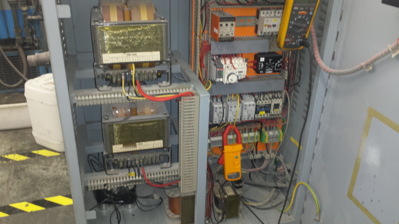
Our contactor supplies 380V off of two legs of three phase system to the primary of a
high voltage transformer. It is for Ultra violet light system on printing press. Previous
to me getting on seen this thing caught fire destroying several contactors and wiring in
cabinet with two other guys replacing components attempting to resurect it.

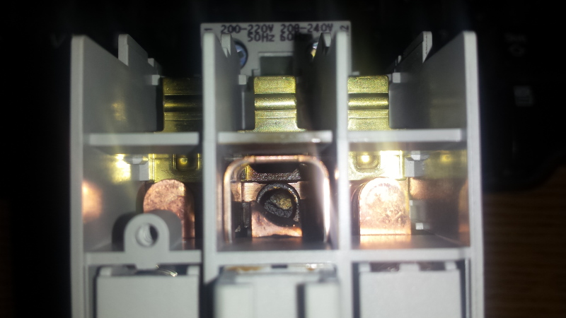
I put the unit in operation while monitoring current. Secondary output at moment of ocurance
was 10 amps, when contactor opens it starts welding melting contacts as seen in pictures.
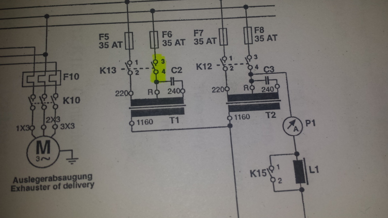
Contactor in question is rated 400V @ 30A. I have posted schematic of circuit, contactor with
issue is K13 and capacitor bank is C2. The four capacitors are 30Uf and connected in Paralel with
accuall measurment of 117Uf.

What is funtion of capitors in this circuit and could they be causing the welding action of contacts?
If I were to connect them in Series for 7.5 Uf instead might that correct the problem?

Thank you, Chuck

20180126_145338_g66h9d.jpg


Replies continue below

Recommended for you

A confusing circuit. It seems as if two independently controlled and protected transformers have the secondaries in parallel.
Is the damage on only one pole of the contactor?
I suspect that when the contactor opens and the transformer is disconnected, the transformer becomes an impedance in series with the high voltage developed by T2. The high voltage is arcing across the open contacts. The current is probably fairly small, but is continuous.


Bill
--------------------
"Why not the best?"
Jimmy Carter
 

Hello Bill, Thanks for your reply. Yes two independently controlled transformers in parallel,
one (K12)operates to warm and maintain bulb temperture. K13 engages when press starts printing.

Yes damage on that pole only.

But wouldn't the primary side of transformer be isolated from secondary side? I don't
understand how this contactor would see the high voltage. An inductive kick perhaps?

Chuck

 
I have no idea what those caps are doing. Strange circuit, I agree with Bill.

It appears you're using 3 pole contactors for switching just two circuits. Use
that third contact by putting it in series with the second one that keeps burning
up. That will double its breaking voltage capacity and may be enough to cure your
contact-frying machine.

Keith Cress
kcress -
 
From the connections and the seeming lack of a return connection other than the connection to Ro I surmised that those may be auto-transformers.
I can't see a second high voltage terminal other that the common Ro.

Bill
--------------------
"Why not the best?"
Jimmy Carter
 
I'm taking a guess that this is an IEC contactor from the style of the drawing and the little bit of the contactor I can see. If it has been sized based on its AC-3 rating then it is almost certainly too small. You should be looking for the AC-6a rating and selecting the contactor based on that. The AC-3 rating is for direct on line induction motor starting. Others are listed here.

What brand is the contactor? Not all brands are equal, even if the rating says they are.
 
Further to Keiths suggestion;
It is important in this application that the third contact be in series with the contact that is being damaged.
It may be good also to wire from the bottom of the middle contact to the top of the third contact and from the bottom of the third contact to the transformer. That will keep the voltage between adjacent terminals at less than would be the case with some other wiring arrangements.
Normally it doesn't matter which pole the third pole is in series with. In this case it is important.
If you can do it safely it may be interesting to measure the voltage across that second pole when it is arcing.
It may be more than double the rated 400 Volts of the contactor.

Bill
--------------------
"Why not the best?"
Jimmy Carter
 
Not my thing, but what I could find...

Is the cap possibly there for if/when the AC coil is swapped for a DC version (i.e., it shouldn't be in there for the current setup)?

Also found this thread on long-length cable capacitance:

All I would ever consider it used for is to smooth out any inductive spikes heading back to whatever is controlling it...


Dan - Owner
URL]
 
Looking at the transformer terminals; R, 220, 240, 1160. This looks like a tapped auto-transformer type ballast. The capacitors are connected between 220 and 240. That would be a 20 Volt winding.
Is this a new problem?
What has changed?


Bill
--------------------
"Why not the best?"
Jimmy Carter
 
I hate people throwing out assumptions involving resonance or harmonics or 'in some way'. And now, that's what I was going to do myself. Sorry for that.

There must be a manufacturer? Or did the thing breed itself into being? That's even worse than assuming resonance. Apart from the 'funny' transformer with a R mid-tap (R could stand for that R-word, hmm...), there is also a partly unconnected secondary winding. Can't the manufacturer be contacted to get some kind of explanation?

BTW, 30 uF is not what you use for 'smoothing out' AC. But it could very well be part of a resonating (I said I was sorry!) circuit. And once you have that - anything can happen.

As Harry Martinson put it in his book Aniara: "The inventor was himself completely dumbstruck the day he found that one half of the Mima he'd invented lay beyond analysis. That the Mima had invented half herself."


Gunnar Englund
--------------------------------------
Half full - Half empty? I don't mind. It's what in it that counts.
 
Thank you Gentelmen! I really appreciate the input. Point well taken Bill I will connect in series as suggested by you and
Keith I feel this should be a significant improvement also noting Scotty's suggestion about AC6a contactor rating, that
makes sence, addionally I will wire K12 the same way. The contactor in question is (ABB standard motor rated I think, not at work currently)
I do find this circuit quite unusall, it's the first time I have come across switching of a transformer like that. I was thinking
they were possibly pulsing the current with the capacitor bank but really don't know for sure. Dan mentioned capacitor possibly
being there for a DC version but I don't think so, however Dan's second suggestion about soothing inductive spikes makes sence.

Bill I walked into this after about four other guy's chiped away at it, first issue lights were not reaching high temp enough to set ink.
Three other times for meltdown thus releasing the magic smoke burning up several contactors and leads, being a Legacy machine compared
to today's standards OEM parts were obsolete and contactor rating could be one major factor. Also the schematic is general to the
production of other machines from OEM, so not very specific to this unit. You are correct about your description of transformer, when I
get to work later I will rewire everything and search for properly rated contactor replacement. I will monitor it's behavior and risk
losing another standard contactor while waiting for properly rated ones to arrive. I will post a picture of the control box later as well.

Laugh out loud Gunner, thanks for adding a little levity to the conversation, in actuality it's four 30Uf caps parallel @ 117Uf, that said
what do you think considering this value, very interested in your thoughts I have great respect for your expertise.

Chuck
 
Thanks, Chuck.
I could talk to the manufacturer. It looks like it is a German thing. And German is my third language. Any name or address? I am getting curious and want to know if I shall drop that R word altogether.

Gunnar Englund
--------------------------------------
Half full - Half empty? I don't mind. It's what in it that counts.
 
I think Bill was right in the first post. If those are autotransformers then opening K13 will put the 1160V from T2 across the contact via the 1160V terminal of T2 to the 1160V terminal of T1, through the T1 winding, across the open K13 contact, through fuses F6 and F8, through K12 and to the R of the other tranformer.

So, putting 2 contacts in series might make it work, but you are still applying too much voltage to the contactor terminals assuming they are rated for 690V.
 
Is it possible that the fuse F5 has blown or the transformer T1 primary opened to allow the full secondary Voltage (1160) to appear at the primary
I think it would act like a choke rather than a transformer.

It is an unusual circuit for sure.
 
I found this on Wiki:
About half-way down, there is a circuit with some similarity to yours. The accompanying text says:

"The semi-resonant start circuit was invented by Thorn Lighting for use with T12 fluorescent tubes. This method uses a double wound transformer and a capacitor. With no arc current, the transformer and capacitor resonate at line frequency and generate about twice the supply voltage across the tube, and a small electrode heating current.[36] This tube voltage is too low to strike the arc with cold electrodes, but as the electrodes heat up to thermionic emission temperature, the tube striking voltage falls below that of the ringing voltage, and the arc strikes. As the electrodes heat, the lamp slowly, over three to five seconds, reaches full brightness. As the arc current increases and tube voltage drops, the circuit provides current limiting"

A UV lamp is a fluorescent lamp without coating.

Gunnar Englund
--------------------------------------
Half full - Half empty? I don't mind. It's what in it that counts.
 
Ah, that explains the cap and answers Dan's next question about ballast. Thank you Gunner!

LionelHutz, forgive my ignorance here but in my mind the primary and secondary are isolated
from each other. I'm not understanding how the 1160 can get to the 380 side. What am I missing?
How does an auto transformer differ in this way? But yes it does have many taps like an
autotransformer.

Roy, the fuses are good and this issue has never caused them to open.

A picture of the control box below, I am going to monitor it after making new connections and
my Dept. big cheese is looking into properly rated contactors. I will post any further developements.

Thanks all, Chuck

20180130_142024_vlb3xd.jpg
 
Waross said:
[/quote If you can do it safely it may be interesting to measure the voltage across that second pole when it is arcing.
It may be more than double the rated 400 Volts of the contactor.]

Due to Bill and LionelHutz theory about high voltage I was second guessing myself so I checked again.
Using high voltage probe just in case. I measured across the second pole from "R" to top of contactor
which gives me a voltage drop of 2.7v, phase to ground gives me 215v and phase to phase gives me 380v.
Currently operation is good ie. not arking, I will monitor it while in operation later, the machine is
down for setup now. Hopefully it does not arch but if it does I plan to have my meter in min/max to see
what I get.
 
Basically an auto-transformer has one shared winding.
In this case the winding will be rated for 1160 Volts between R and 1160.
The winding is tapped at 220 Volts and at 240 Volts.
The R-220-240 Volt portion of the winding is often but not always a heavier gauge wire.
With the contactor open, there will be a direct connection through the winding from 1160 to R.
The transformer will now act as a choke in series with 1160 Volts fed from the other transformer.
The current will be limited by the impedance of the winding but even a small current will do a lot of damage if the arc is continuous.
But a more important issue is:
Why does a circuit that has worked for years suddenly develop these issues.
Something must have changed.
OP said:
Bill I walked into this after about four other guy's chipped away at it, first issue lights were not reaching high temp enough to set ink.
Considering this, quite possibly one of the ballasts/transformers is failing.
The circuit was somewhat strange.
With a component failing the circuit is now somewhat strange with added arcing.
We have been concerned with the arcing.
I suspect that we are treating a symptom rather than the root cause.
My first rule of trouble shooting is:
"Find out what the root problem is first."
We may be concentrating on a symptom and not the root cause.


Bill
--------------------
"Why not the best?"
Jimmy Carter
 
Status
Not open for further replies.
Back
Top