Eng-Tips is the largest engineering community on the Internet

Intelligent Work Forums for Engineering Professionals

Some advice please, Contactor Meltdown 7

Status
Not open for further replies.

flexoprinting

Electrical
Sep 22, 2007
239
0
0
US
20180126_130732_fcbywb.jpg


Our contactor supplies 380V off of two legs of three phase system to the primary of a
high voltage transformer. It is for Ultra violet light system on printing press. Previous
to me getting on seen this thing caught fire destroying several contactors and wiring in
cabinet with two other guys replacing components attempting to resurect it.

I put the unit in operation while monitoring current. Secondary output at moment of ocurance
was 10 amps, when contactor opens it starts welding melting contacts as seen in pictures.
Contactor in question is rated 400V @ 30A. I have posted schematic of circuit, contactor with
issue is K13 and capacitor bank is C2. The four capacitors are 30Uf and connected in Paralel with
accuall measurment of 117Uf.

What is funtion of capitors in this circuit and could they be causing the welding action of contacts?
If I were to connect them in Series for 7.5 Uf instead might that correct the problem?

Thank you, Chuck

20180126_145338_g66h9d.jpg


Replies continue below

Recommended for you

If it's a 50Hz designed system operating on 60Hz then that would be messing up the T1-C2 resonance circuit that was tuned for operation on 50Hz.

 
Thanks Bill, I assume these rules apply to AC applications only while DC drives might be completely different.

219V across R and 220 on T2 xfmr- all terminals 1 Through 7 reading 219V terminals 8 through 10 @ 148V

219 across R and 220 on T1 xfmr- all terminals 1 Through 7 reading 219V terminals 8 through 10 @ 158V

219 across R and 220 on both xfmrs and jumper across both 1160 terminals I could see no current moving
or circulating between transformers.

I started the system up and allowed both transformers and bulb warm up.
T2 had 5.1 amps
T1 had 4.7 amps
Voltage across capacitor bank measurment taken at 420 and R = 412V on T1 and T2
Current draw on T1 caps = 19.4Ma
Current draw on T2 caps = 19.2Ma

Lionel, most of our German equipment has 50/60 Hz on data plate but not this one. It's 50Hz.
I assume this affects the frequeny of resonance, by how much? Really wish I had a HV probe
for my scope. Those portable Flukes are nice but spendy.

I added another picture first one not very clear, sorry about that.

Chuck


xfmr_f2iuy3.jpg
 
I don't quite understand your readings.
I'll give the sequence; Note: Let's round up the 219 Volts to 220 Volts for simplicity.
Apply 220 Volts across R and 220.
You should see the following readings with the capacitors disconnected:
Terminal R to terminal 360,- Should Read 360 Volts
Terminal R to terminal 380,- Should Read 380 Volts
Terminal R to terminal 400,- Should Read 400 Volts
Terminal R to terminal 420,- Should Read 420 Volts
Terminal R to terminal 1160,- Should Read 1160 Volts

No circulating current is a good sign. Many of the common faults would result in a circulating current.

You may want to do this test with the lamps disconnected.
I suggest energizing both ballasts and letting them sit, energized for long enough for the temperature to stabilize.
Then check that the voltages are what they should be and check for circulating current.
We want to rule out a ballast breaking down when hot.
Do this test with the capacitors disconnected. If the ballasts pass, do the test over with the capacitors


Bill
--------------------
"Why not the best?"
Jimmy Carter
 
All -

I think we're over-thinking this one. Capacitors, transformers and discharge lighting are all horrible loads to switch. Most NEMA contactors will handle this, but most IEC contactors won't unless they're chosen for severe service. This is an AC-5a, 6a or 6b switching duty - discharge lighting; transformer switching; capacitor switching respectively. If you use an AC-1 or AC-3 rated contactor in this sort of service it will have a short violent life. Look at the de-rates applied to IEC contactors for the more severe duties: it normally forces a jump of at least one frame size and occasionally two. I really think this contactor is simply under-rated for the job it is being asked to do.

Last year we picked up on a similar problem with a group of AC-3 rated starters being used in inching duty, and every now and then we'd see a starter bucket burn up. They were only built for DOL starting, and we were hammering the life out of them. I've had them rebuilt as AC-4 starters using a much heavier contactor and the problem has gone away.
 
Good Morning

Ah yes the challenges of communication with interpretation differences, Sorry Bill my bad. I interpreted across as one of the three legs @ 220v across those two terminals, I was thinking you would have said 220v through "R" and "220" so what your saying is I should have a neutral on "R' and one leg of 220v to the terminal. Which presents another problem I need to correct to make this thing safe. Whoever installed this machine only brought in four wires and the fourth wire is connected to ground of cabinet!! There is no connection for neutral!?, I followed the supply conduit to a 480v Delta to 380v wye transformer which should have five wires going to machine, I need to open supply panel when I get to work and see where that forth wire is really connected and don't know may need to check xfmr connections
also. If that fourth wire is connected to neutral in xfmr and I get impedance on any of the three leads this would make the cabinet hot correct?

Yes Scotty I think your correct It's looking like the contactor is probably the cause because when I checked voltage ratios a while back with it connected 380, they seemed reasonable. I do want to make sure these things are balanced though and will perform the test as Bill suggested to remove all doubt I will try to get it right this time though. Thank you for pointing out the NEMA/IEC differences which could be substantial.

Thank you Lionel, is this difference enough that I should be concerned about?

Chuck
 
My bad. Your original diagram showed a 220 Volt feed. I overlooked (forgot) The picture showing the 380 Volt feed.
You can supply 220 Volts between R and the 220 Volt terminal or 380 Volts between the R and the 380 Volt terminal.
Either way you should see the correct voltages across R and the other terminals.
Scotty. I agree with you.
But it took a little while to get here. Once here, I thought it prudent to check that there was no problems with the ballasts.
I have been thinking that it is probably a contactor issue but not saying it. Once it has been said that;
"It's most likely a contactor issue." There is a great tendency to overlook signs that it is actually something else.
But now it has been said, (I was very close to saying it myself.)
If the final round of tests look good, then we can adress the contactor issue.
At that point I will happily defer to your advice. You are a lot closer to IEC land than I am.
Two issues with the contactor;
1. The high voltage backfeed. Keith's suggestion may solve that issue.
2. The contactor may still be underrated swithcing 380 Volts to a ballast.
Back to you.

Bill
--------------------
"Why not the best?"
Jimmy Carter
 
Lol, well I must have both shirt and hat on the way then. I performed another test after pulling my head
out of you know what.


With 380 L1 connected across transformers 1&2 on the 380 terminals.
L2 connected across terminals "R" for a 380v supply to both transformers.

Transformer 1 Transformer 2
----voltage reading---

1. 199.6----199.3

2. 217.1----217.2

3. 233.3----234.4

4. 249.7----250.2

5. 216.1----216.2

6. 1097----1099

7. 112.4----112.5

8.201.9----204.1

9.212.7----214.5

10. 223.3----225.2


All readings are very close to same, I think variation showing might
be due to other loads in building and time taken to move probes causing voltage to deviate slightly.

I did repeate the current circulation test (correctly this time) and seen some current flow.
R to R lead was @ 410Ma
380 to 380 was @ 400Ma
1160 to 1160 was @ 30Ma

We received our quote for ballast $5,800 .00 Yeow! Hopefully you are going to say they are good Bill.
Was talking to my Manager about it and he remembered saving pictures of OEM contactor that burned up in fire.
It's only rated for 600V, I also included the first time it let the gremlin loose.

W_D_214_UV_Pic_of_Side_of_Schiele_DL_7K-4H_Label_zpsugt.jpg
W_D_214_UV_Electrical_Panel_Fire_Damage_Picture_teccwt.jpg
 
wowwee! That was a nasty gremlin..

BTW Nice testing. You won't find closer matching than that in the real world.

What I think is happening is the contact opens and depending on where in the power
line cycle you get a huge arc as a lot of energy is stored in the magnetics or a not so big arc otherwise.
This causes the very classic "It worked for a year then did this!" result. Replacement and repair results
in some utterly random period before, "It happened again!"

This is the kind of thing often seen with wye-delta motor starters. Runs for a year then trips the breaker.
Runs for a month and trips the breaker, then runs for 2 years and trips the breaker. Lots of head scratching.

A snubber across the contact would limit the voltage available to arc, to something considerably lower AND
would provide someplace to dissipate the energy over a large surface area - the resistor in the snubber circuit.

Any arc that did occur would be shortened in period to something dissipatable by your contacts. What you have
now is a case of if the arc is a peak-energy arc then the contact metal gets so hot as to significantly
vaporize into the gap. It then participate in the arc plasma reducing its normal air-gap resistance down to something
shockingly low. In that state with more and more contact metal joining the party it becomes impossible for the
arc to ever extinguish because now the contact-space may have only 40~70Vac of interruption ability. This
continues until there is actually no further contact metal present to continue the arc. If you're lucky
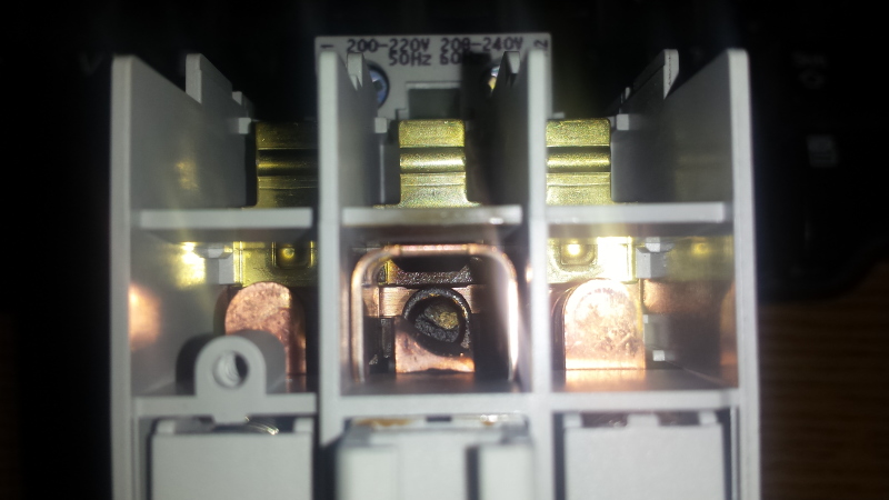
you get what you just got. If you're not lucky you get what your latest picture depicts.

Even worse, the heavier duty the contactor is the worse the results because there is more contact metal available
to maintain the plasma. A heavy duty relay will give the latest picture results because you had ~2kW dissipating
in that space for maybe 20 seconds whereas the latest failure with perhaps a lesser contactor had exactly the
same power dissipation but ran out of metal sooner (10 seconds?), hence less damage.

Realize that when AC arc welding with a stick welder the substantial arc length is not much less than 690V contactors
can provide and that once the metal of the 'stick' is spewing into the arc the arc voltage drops to only 50~70Vac.
Picture an arc welding arc between your contacts. The final results would look just like what you have.

You need a snubber to limit the arc time and to suck up the stored inductance energy.


Keith Cress
kcress -
 
Sorry Keith, I beg to differ.
Remember that when only one contactor opens There is over 1000 volts across that one pole. The current is limited to a low value by the impedance of the ballast, but it does not take much current to do a lot of damage if the arc is not interrupted.
The original contactor had a 660 Volt rating. The replacement may only be rated for 400 Volts.
With 1160 Volts across a 400 Volt rated contactor you don't need inductive kick to maintain an arc.
That last picture looks like sustained arc damage.
I support your first excellent suggestion to connect two p[oles in series.
It could be that there are voltage fluctuations on the grid, and whenever the contactor is opened with the grid voltage on the high side of the tolerance, the 1160 Volt feed back is not interrupted and we have the sustained low current arc.
I find that oversized contactors have more of a cooling effect on the arc as a result of the greater mass of the contacts.


Bill
--------------------
"Why not the best?"
Jimmy Carter
 
Hi Keith

Keith, would a snubber be a problem during normal operation since they are connected across phases? I understand those to divert high frequency signals or high voltage spikes and sense we need the resonant circuit and high voltage a Low pass or high pass filter would not work either way? Or are you thinking a four pole contactor w/nc terminals to bring it into circuit when contactor opens?

Chuck
 

Thank you everyone for your valueable input on a circuit which was humbling not only for me
but five other Techs as well. I now have greater insight obtained by the comments and doing
a lot of googling even learning about material properties coupled with manufacturing of contact
material.

The solution was simple, getting there not so much. A real smack myself in the forehead moment!

Chuck
 
Status
Not open for further replies.
Back
Top