Continue to Site

Eng-Tips is the largest engineering community on the Internet

Intelligent Work Forums for Engineering Professionals

  • Congratulations KootK on being selected by the Eng-Tips community for having the most helpful posts in the forums last week. Way to Go!

Some advice please, Contactor Meltdown 7

Status
Not open for further replies.

flexoprinting

Electrical
Sep 22, 2007
239
20180126_130732_fcbywb.jpg


Our contactor supplies 380V off of two legs of three phase system to the primary of a
high voltage transformer. It is for Ultra violet light system on printing press. Previous
to me getting on seen this thing caught fire destroying several contactors and wiring in
cabinet with two other guys replacing components attempting to resurect it.

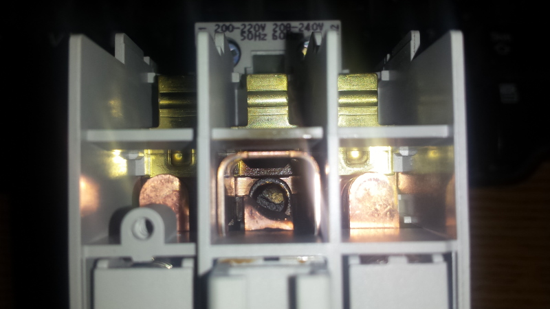
I put the unit in operation while monitoring current. Secondary output at moment of ocurance
was 10 amps, when contactor opens it starts welding melting contacts as seen in pictures.
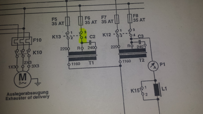
Contactor in question is rated 400V @ 30A. I have posted schematic of circuit, contactor with
issue is K13 and capacitor bank is C2. The four capacitors are 30Uf and connected in Paralel with
accuall measurment of 117Uf.

What is funtion of capitors in this circuit and could they be causing the welding action of contacts?
If I were to connect them in Series for 7.5 Uf instead might that correct the problem?

Thank you, Chuck
20180126_145338_g66h9d.jpg


Replies continue below

Recommended for you


That is what you said the first time Sir! except you used a few more fonts to get it through this thick head of mine. I did megger
these things before but I suspect I overlooked something, testing for impedance does present it challenges in comparison to simple
resistance testing. I will do some reading and see what I can do to perform a more deffinative test on both of these.

I did confirm what you said, with contact open there is HV on "R" terminal, the appearance of this thing even had me fooled as it
appears to have two windings. I would like to get hold of a diagram of it unfortunatly it does not have a data plate for more info.
Thank you Bill for the eloqent correction.

Chuck
 
So what was the first issue that started the whole mess? Is it possible a contactor failed due to use and the replacement picked was not high enough voltage rated?

You measured when K13 was open and K12 was closed?

I'm also curious why the transformer tap is labelled 220 implying it is a 220V rated tap, but the setup is applying 380V to it. It just seems odd.

 
Yes Lionel very possible, and just as important not rated for transformer switching (ac-6) I was not involved when that occurred and as I
understand it auto transformers like these are susceptible to short circuit damage.

Yes k13 open and k12 closed, many of our machines are purchased used and some come over from Europe so reassigning tap locations to
compensate for voltage is common around here. Forgot to add that the schematic is general to all similar machines manufactured by
Thiemer if you were to zoom in on picture of control box you could see the tap is actually on 400V input so 380 is within acceptable
10% allowance I think.

Chuck
 
Good catch Lionel. I missed that.
However in the latest photo it appears that, wiring diagram to the contrary, the ballast is actually connected to the 380 Volt tap and the capacitors to the 400 Volt tap. That connection will put the same 20 Volts across the capacitors.
flexoprinting: You may want to try measuring the primary and secondary currents of both ballasts when both are energized.
Have you checked for an open or shorted capacitor?
You may wish to try a "Poor man's" impedance check.
Disconnect all leads to a ballast.
Check for continuity between R and 1160.
Use terminals R and 1160.
Connect a 100 Watt lamp or other suitable resistor in series with the ballast (R-1160).
Apply 220 Volts to the series combination. Measure the current and the voltage drop across each ballast in turn.
The currents and voltages of the two ballasts should match closely.
If the results are indeterminate, vary the value of the series lamp or resistor.
Try this test with the capacitors connected and again with the capacitors disconnected.
Shorted turns will often give more of an indication with this test than with a resistance test.
You probably want a resistance that will cause a minimum of about 10% to 20% at least of normal secondary current to get into the more linear area of the core magnetizing curve.

Bill
--------------------
"Why not the best?"
Jimmy Carter
 
I did check caps with meter it's supposed to see ~120Uf I get 116Uf on one bank and 117Uf on the other.
Thank you for that tip,I will do exactly as stated and check results. I was kind of racking my
brain to see what I could do for test and thinking I could bring my function generator and scope
to work if I had to. Not sure I would get acceptable results though.

Thanks again Bill

Chuck
 
Hi Bill

I think it looks good but will wait for your thoughts on findings.
I moved the tap from 400V to 380V and gained 67V on the 1160V output currently at 1117V.

Caps checked.

There is continuity between R and 1160 on both ballast.

My greatest challenge was finding a 100 watt bulb in an industrial setting, first test was 60watt.
All test were performed at 217V

Voltage drop across R and 1160>>>>>T1= 1.4mv T2= 1.3mv

Current through 60watt=24.2ohms>>>T1=0.38ma T2= 0.54ma
----------------------
next two test performed with halogen lamp for resistance of 3.9ohms

Voltage drop.>>> T1= 1.4mv T2= 1.3mv
Current>>>>>>> T1= 0.50ma T2= 0.46ma
----------------------
this test with caps installed and same 3.9 ohm bulb

Voltage drop>>>T1= 0.9mv T2= 1.4mv
Current >>>>>>T1= 0.36ma T2= 0.41ma

Chuck
 
We didn't have high enough current. Those results are somewhat indeterminate.
However they are not that good.
I hope that both transformers were at the same temperature when the tests were done.
Another suggestion.
Apply 217 Volts across R and 220. Check the voltages at the other terminals for the proper ratio and compare with the second transformer.
With one transformer hot and one transformer cold we may see a 10% difference but not with both transformers at the same temperature.
I note also that the caps cause a 28% change in current on one transformer and only a 5.8% change on the other transformer.
Is it possible to measure the current that the caps are drawing in circuit after they have warmed up? That is a better test than a meter test. It often will show a problem due to breakdown under working voltage.
Are those the original contactors or have they recently been changed?


Bill
--------------------
"Why not the best?"
Jimmy Carter
 
As a precaution we are moving on a quote for new ballast. My manager was refered
to a Theimer rep in Florida who basiclly is a parts salesman with no knoweledge of electrical system and could offer no intel. I really
like the quality of German equipment communicating with OEM can be a little challenging sometimes though.

Yes both were @ same temp and I waited for my meter to settle on all measurements, also the resistance reading is of the entire series rig
I put together. I wanted to be as accurate as possible.

I will perform test on Monday and post results, Yes the whole circuit drops two amps when bulb/transformer heat up. Also I need to measure
transformer amps individually yet as you requested so will do that. Press needs to be in motion though or I cook the product belt, I'm
at the mercy of schedualing of runs.

I will attemp cap current also, no these are underrated brand new abb contactors (working on that) I think the temperary California conection will
suffice for testing purposes as long as I'm here to shut it down.

Thank you Bill

Chuck
 
Will the ballast under consideration be an exact replacement for the existing ballast?
We can have new issues with circulating currents if the ballasts are not matched.
If you can not get an exact replacement it will be well to replace both ballasts with a pair of identical ballasts.
But first, do you know the manner of the failure of the original contactor?
It may be that the contactor was able to withstand the high feedback voltage and failed due to age.
A worn or broken component may have reduced the clearances and led to the first arc-over.
If the issue is the contactor rating, then itsmoked's suggestion of contacts in series may be the solution.
However I would be more confident had the test measurements been more closely matched.
What to do next;
1> Disconnect the high voltage leads.
2> Apply 217 Volts to the R and 220 Volt terminals and check the voltages on all taps of both transformers. Disconnect the capacitors before this test.
3> Connect the high voltage jumper between the two 1160 terminals and energize both transformers. Check for a circulating current between the transformers.
4> Check the capacitor current of each group of capacitors. If the currents are within 15% to 20% there may be no need to check the individual capacitors.
5> If all the tests give closely matching results it is a strong indication that the original issue was the failure of the original contactor and the replacement with a contactor with a lower voltage interrupting capability.
Note: when checking the current drawn by the capacitor groups it is well to also check the voltage across the capacitors.

Bill
--------------------
"Why not the best?"
Jimmy Carter
 
They will take three weeks to build and come from Germany, so probably not worth the risk of a mismatch. I will have them order as set,
good point. Thank you Sir!

The first issue they had was bulb not getting hot enough which was caused by improper cycling of cooling fan. My guess maybe a month later the OEM contactor cooked possibly due to age but maybe due to ballast failure as you suspect and was replaced with improperly rated one which cooked again and again. There were two owners of an electrical company from down the road working on it, very smart guys but they were fooled by the readings and such as well. The bulb is a voltage hog and drops 600V across it so simply probing xfmr output with HV probe you only see something like 284V. I have the typical HV probe from Fluke like they used, I was not clever enough to read voltage across "R" and 1160 for fear of manipulating that tiny alligator clip to the "R" terminal and taking a hit. ( I should have powered it down and made my connections, that reading would have help me understand the output more )I suspect they did the same thing because they had the same dumb look on their face that I have.

Currently itsmoked suggestion (which I have dubbed the "California connection" Keith lives there I think) has been working great however, getting to the root cause as you suggest is our goal and I may still use Keith's idea on new contactor anyway. Should the test prove ballast acceptable and we figure out it was just a retiring contactor is fine. Thanks to you folks I will know how to troubleshoot it next time.

I will post the results of test hopefully on Monday schedual permiting, Thank you Bill.

Chuck
 
Good luck. Glad to help.

Bill
--------------------
"Why not the best?"
Jimmy Carter
 
LOL That's what I guessed when I saw the "CA-connection".
Yep, Santa Cruz ~ 70mi South of San Francisco on the ocean.

You might as well use two contacts if one is unused.

Since this beast is only single phase lets hope that middle phase isn't a stinger phase..


Keith Cress
kcress -
 
Stinger phase?

You 'murcans sure do some strange things to your electrons. :)

We don't have any equivalent to that in Europe.


On a slightly more serious note, if this is a 50Hz machine running on 60Hz then the L1 reactor is going to drop 20% more voltage than it is intended to. The transformers will be OK running with 80% flux density in the core which will make up for the 20% increase in hysteresis losses.
 
You know one when you see one. I was asked to have a look at a spot welding machine that mysteriously failed in some installations and worked well when moved to Another Place.

The stinger phase caused the problem. I mailed the producer (European) and, at first, they didn't believe me.

Problem eventually solved by adding a note on the first page saying that the welder needed a full and symmetrical three-phase supply.


Gunnar Englund
--------------------------------------
Half full - Half empty? I don't mind. It's what in it that counts.
 
quod erat demonstrandum!

I run into that problem with CNC machines quite frequently. They all have a control transformer that
provide all the power for the PLCs, controls, trajectory planners, etc. Frequently there's a stinger
or "Wild Leg" then, inevitably, someone picks the stinger for the control transformer. Other times the
VFDs pick the stinger to monitor the voltage and the drives frequently trip off-line on 'bad voltage'.
Rolling the phases often solves these problems or I select a different phase for the single phase control
transformer. I've never been real comfortable with open delta feeding drives. Motors don't care at all
but I'm not sure the rectifier front-ends can happily distribute their loading correctly.

That's why I bring up the 'stinger' on the cockamamie ballasts used in Chuck's machine.

Keith Cress
kcress -
 
Right, Keith.
You need a delta winding to leave a low-impedance route for the triplenes (3rd, 9th etc) harmonics. If the grid cannot deliver that, you get exactly that problem with "bad voltage" messages.
But not at all sure that it causes a problem with a single phase load applied line-line. There, the impedance should be OK. Triplene impedance is already low enough and it would be a lousy transformer if it cannot handle the light (pun!) load of a lamp circuit.

Gunnar Englund
--------------------------------------
Half full - Half empty? I don't mind. It's what in it that counts.
 
We do have machines in house w/high leg but not this one and those were my thoughts the empty contact is present why not use it for additional prevention.

Interesting observation by Scotty it is a 50Hz machine, not sure I'm smart enough to understand Hysteresis losses and the associated effects but do those loses matter since the transformers are also coils and would see the same losses? making the whole circuit equally functional whether on 50Hz or 60Hz? Reactors are for current limiting doesn't this introduce impedance into the circuit exacerbating the potential for contactor to arc as Bill described? Forgive my lack of knowledge fella's I'm looking at a forest and you folks have the ability to see trees within the forest.

Chuck
 
Transformers and motors are concerned with the "Volta per Hertz" ratio.
Your 50 Hz machine, on the 380 Volt tap has a 380V/50Hz = 7.6 Volts per Hertz.
At 60 Hz and the 380 Volt tap the applied V/Hz ratio is 6.3 Volts per Hertz. It is lower than the machine wants so you are okay.
Now if the machine was intended for 380 Volts and 60 Hz the V/Hz ratio at 50 Hz would be too high and the motor or transformer would be in danger of saturation and overheating.
This is a whole other topic for discussion that fortunately you mostly don't have to worry about going to a higher frequency at the same voltage. Reactors will have a higher impedance and capacitors will have a lower impedance but if the machine worked for a number of years before failure there is probably not an issue.

Bill
--------------------
"Why not the best?"
Jimmy Carter
 
So if it were designed for 60 Hz and needs to see 7.6V per Hz it would need a supply of 456V and at 50Hz
that would be 9.12V I think I understand. And yes another topic, I don't want to get off on a tangent.

Thank you Sir!
 
Don't exceed the V/Hz ratio that a device is designed for. You may either lower the voltage or increase the frequency without exceeding the ratio.
A transformer may be operated at a lower voltage than it was designed for or a higher frequency than it was designed for.
A motor does not like low voltages. Raising the frequency on a motor is equivalent to dropping the voltage as far as torque is concerned.
hen we convert motors between 50 Hz and 60 Hz, we try to adjust the voltage in the same ratio so as to keep the same Volts per Hertz ratio.

Bill
--------------------
"Why not the best?"
Jimmy Carter
 
Status
Not open for further replies.

Part and Inventory Search

Sponsor