rollingcloud
Aerospace
I have two spline parts that's used in high load environment. I have MOW & MBW inspection data for both external & internal splines, is there a formula to deduct plating thickness from the MOW & MBW? So I can confirm the class of the spline.
Internal spline Sleeve - Fillet root side fit - ANSI - CLASS 5
number of teeth 27
Face width: 1.4
spline pitch 16/32
pressure angle 30
base diameter 1.461418
Major Diameter(max) 1.816
Form Diameter 1.754
Minor Diameter 1.625
MIN EFF CIR SPACE WIDTH 0.0982
MAX Actual CIR SPACE WIDTH 0.1011
The internal spline was nitrided to ~57 HRC.
EXTERNAL fillet root side fit spline: class 5
Face width 0.25
number of teeth 27
spline pitch 16/32
pressure angle 30
base diameter 1.461418
Major Diameter (max) 1.750
Form Diameter 1.621
Minor Diameter 1.564
MAX EFF CIR Tooth thickness 0.0982
MIN Actual CIR Tooth thickness 0.0953
External spline shows no case hardening evidence and has core hardness of ~44 HRC
Would it better for their hardness to have smaller difference? I wonder why the external spline was not case hardened.
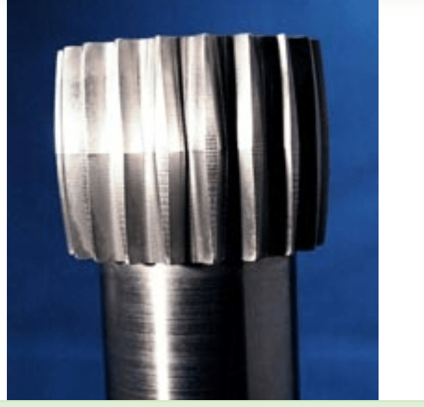
The mating external spline has average lead crowning of 0.0031, lead crowning inspection of the internal spline (see the standard spline data above) shows 0.00005 - 0.00036. Plating thickness: 0.0003~0.0005, can the lead crowning just be the variation of the plating thickness? How do I know if it was an intentional design? From this article, they did a lead crowning of 0.0002 on helical gear.

