Continue to Site

Eng-Tips is the largest engineering community on the Internet

Intelligent Work Forums for Engineering Professionals

  • Congratulations IDS on being selected by the Eng-Tips community for having the most helpful posts in the forums last week. Way to Go!

Some motor fun, help and guidance required 2

Status
Not open for further replies.

AndyLas

Computer
Jul 4, 2019
7
Hello chaps,

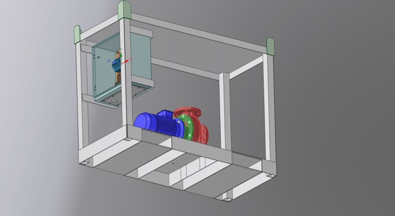
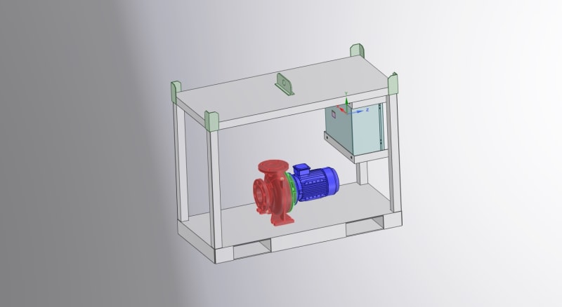
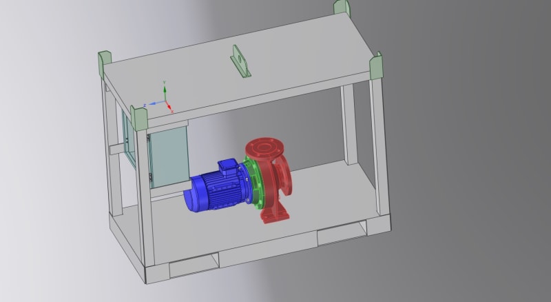
I have a water pump attached to an 11Kw 3 Phase motor ( Tested with a VFD and works ok )

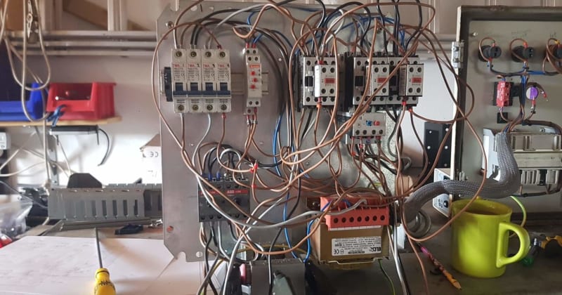
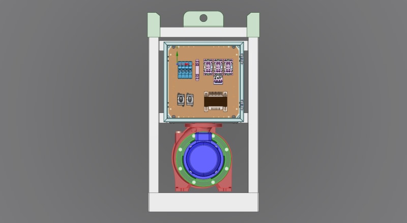
Attached to the frame of the pump assembly is a panel containing the following:

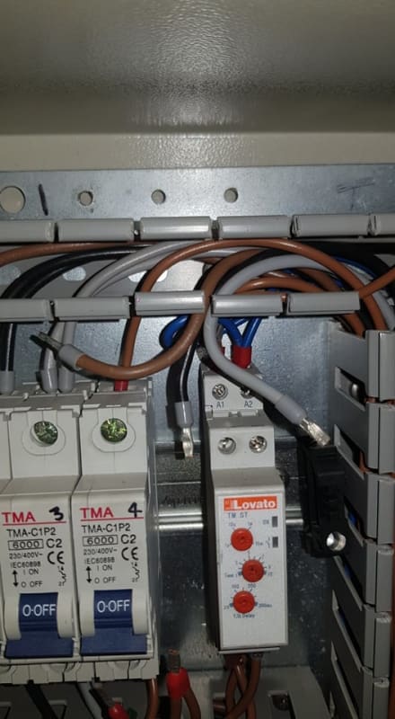
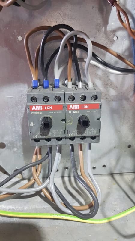
2 X ABB OT32E3 ( Power Switches )
3 x Lovato BF2510A400 ( Contactors )
2 x Lovato BFX10 02 ( Add on blocks )
1 x Lovato BFX10 11 ( Add on Block )
1 x Lovato RF381400 ( Thermal relay )
1 X Lovato TMST ( Time relay )
1 x 400V to 240V Ac Transformer

In the door are:

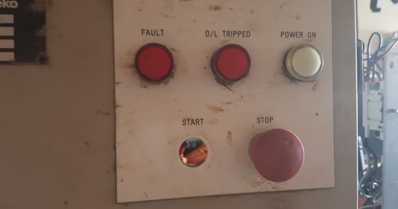
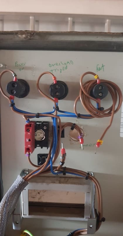
3 x Led Indicators ( Power On, Fault, Overload Tripped )
that are :
1 x TMA-AD22-TW-230 230V Led Indicator
2 x TMA-AD22-R-230 230V Led Indicators

1 x MT AA20 Analog 20 Amp Meter
1 x MT AH 230 Hour Meter
1 x E-Stop switch

1 x Missing start switch.

Q1. Anyone recognise this kit list and have an idea what the missing part could be.
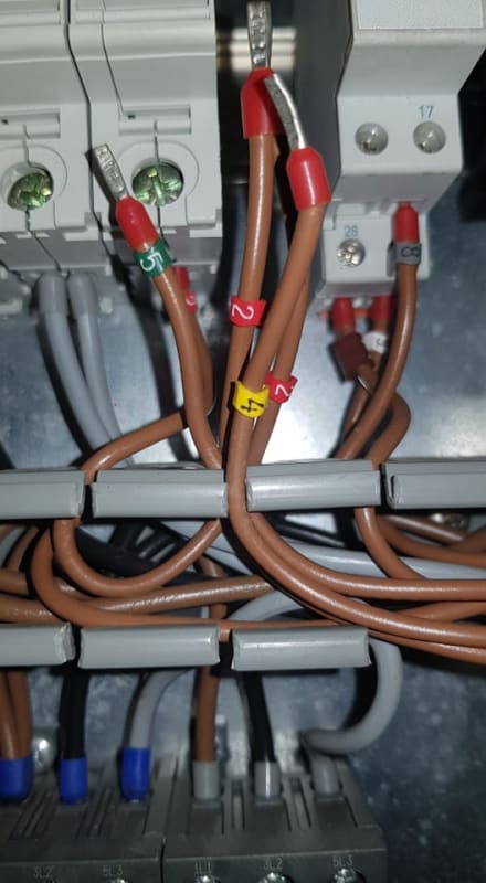
One of the cables at the missing part has a tagged (4) which goes to the Fault Led on the door panel.

Q2. Also the ABB switches look a little oddly connected up and if both were switched on the phases would short out, Any idea why that is?

All the best to you all.

George.


66025179_350422985641571_3480452088620646400_n_hjgvgj.jpg
64573315_348726972485791_1775866705134747648_n_qnerhh.jpg
65688581_369065500360175_7427073369134071808_n_cfzl8q.jpg
65755412_610722112754784_1944772904004616192_n_h9gwqo.jpg
65781809_2059321624370704_7297533865541763072_n_f1clbj.jpg
 
Replies continue below

Recommended for you

Need some backed-out pictures. We need more of the panel to flesh-out it's particular style.

And what's the VFD got to do with anything?

Keith Cress
kcress -
 
Hi Kieth,

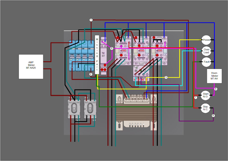
I am in the process of creating a diagrame.

It was a lot tidier until i took out the cable management bars.

is this image any use, most photos i took are close up.


received_364644954467956_hch5kf.jpg
 
That helped.

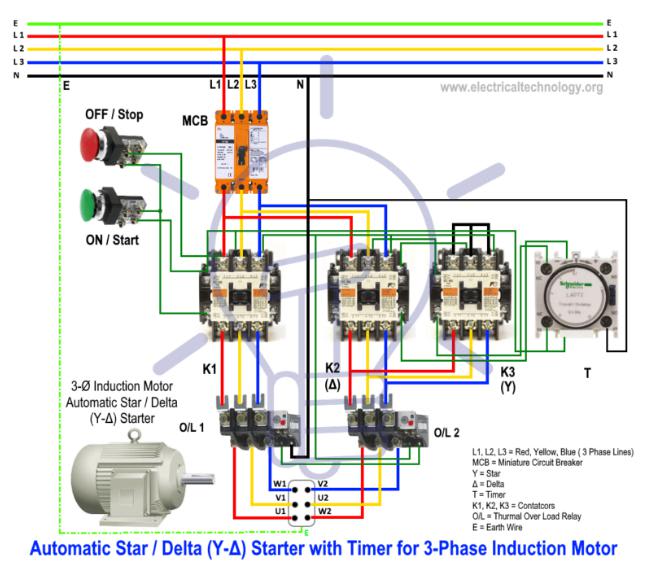
Looks like those three contactors on the right make up a star-delta starter. S/D starters require a timer or two.

See if the wires appear to mach up with this:
SD_starter_htxyzq.jpg


The timer for it is that device to the right of the blank spot.

I'd say what's missing is another breaker. They also get grabbed more than about anything else in there. Why is this system removed? What are you planning to use it for?

Scratching my head on those ABB switches. Where's their actuators? What do they look like. Are they mechanically interlocked?

Keith Cress
kcress -
 
Hi Keith,

The ABB switches have no mechanical connection to prevent both being turned on the same time and blowing the wires.
I read that this is used to reverse a motor, I would never need to do that so I most likely will remove one.

Yes, the diagram you posted is identicle, I am in the process to draw it now.

I suspect the missing part was a second timer.

Connections_cejzwd.jpg
 
Might have been a timer to blink the fault light.

You said this was a pump panel. Why would it have had reversing?? That is exactly how those switches are wired.

Are there no operators from the front panel? I'm suspecting not as I don't think you can fit the operators that close together. If there aren't then the switches were probably set up to one-time correct the pump direction of rotation.

Keith Cress
kcress -
 

Yes it is for a pump, I am not even sure if the pump would work in revearse, it is indeed bizzare. I will most likely remove the extra switch connections for safety and keep it in place as a spare.

Likely what I will do is re-wire it in a more conventional way, more according with the images you kindly uploaded, at least then all the details will be known, Not much would change actually.

I hoped the missing part would be known by somebody and just drop it in and not need to change anything. I ordered a new panel start switch already.


It seems like I ran into a factory wired submersible pump panel yrs and yrs ago that was fitted w/ a reversing starter (more than likely jogging) that could be used in an attempt to clear a clogged pump instead of having to pull it.
 
Automatic reversing contactors are common on electric "Reefer trailers".
When moving these units are powered by an onboard diesel generator.
When loaded with product and parked at the terminal they are powered by shore power.
There is a phase rotation relay which energizes the proper contactor so that the compressor always turns the same way.
Is this a portable or a relocatable pump skid?

Bill
--------------------
"Why not the best?"
Jimmy Carter
 
Finally the missing part has been identified which also makes sence of the phase reversal switch.


If the phases are incorrect, this phase monitoring relay will not allow the system to power up and as connected would enable the fault LED.

The operator can then changed the ABB switch to the correct phase combo and the fault led would go off.

Smart actually.
 
When moving these units are powered by an onboard diesel generator.
When loaded with product and parked at the terminal they are powered by shore power.
There is a phase rotation relay which energizes the proper contactor so that the compressor always turns the same way.


Great sleuthing, Bill.

Muthu
 
Hi Bill,

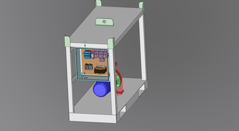
Yes, it is in a transport frame, a big but portable pump assembly. Well maybe not so big as you guys deal with, this is an 11KW motor driven unit.

I will upload some cad drawings i created of it.


Those contactors should have a mechanical interlock of some sort.
If not, consider replacing then with an interlocked device.
Or.-
Consider retaining one of the disconnect switches and adding an interlocked set of contactors controlled by your phase rotation relay.
And thanks for the kind words, friends.
Bill
--------------------
"Why not the best?"
Jimmy Carter
 
Status
Not open for further replies.

Part and Inventory Search

Sponsor