Continue to Site

Eng-Tips is the largest engineering community on the Internet

Intelligent Work Forums for Engineering Professionals

  • Congratulations KootK on being selected by the Eng-Tips community for having the most helpful posts in the forums last week. Way to Go!

Speed Control of Single-Phase Induction Motor 3

Status
Not open for further replies.

sham96

Automotive
Apr 15, 2019
35
Hello Everyone!

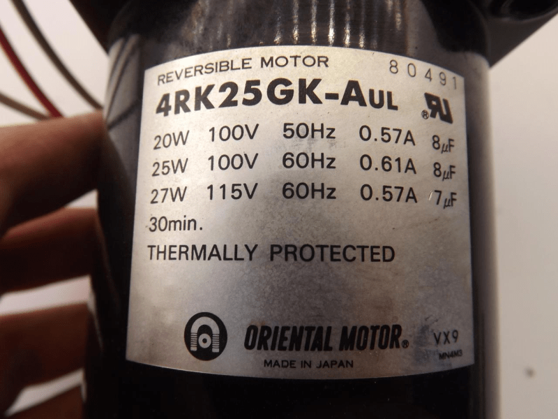
I have a single-phase reversible induction motor with the following specifications:

Model : 4RK25GK-AUL
Rated Power: 20W
Rated Voltage: 100V
Rated Current: 0.57A
uF : 8

I am looking for a way to control its speed. Can I use a dimmer switch or a fan-speed control switch to do this? Or is there a better alternative?

Any help is appreciated!

 
Replies continue below

Recommended for you

Nope. No can do. That is a fixed speed motor.

You either need to use a 3 phase motor and a VFD
or
A DC motor with a speed controller
or
A brushless motor with a matching drive unit.

Keith Cress
kcress -
 
Oh alright Sir, That is indeed a bummer! Thanks for your feedback :)
 
@3DDave Sir from what I know it is not advisable to use a single-phase VFD for single-phase IM since these motors are wound differently than a 3 phase motor.
In order to use a single phase motor with a VFD, the motor must be inverter grade, which means paying to have the existing motor rewound, or purchasing a new motor. Also it is less expensive to upgrade to a 3 phase motor for use with a VFD.

 
I'm just curious as the motor can run either 50 or 60Hz, but there are some single phase motor types that cannot accept a VFD; I'm just curious how one identifies this as a motor that is not suitable from the limited information on the Internet. I don't know that magnetics know anything about 'inverter grade' as opposed to dirty power situations.
 
You can run a 'non-VFD' grade motor on a VFD as long as you are under loaded and don't vary the speed too much.
And you usually need to add additional cooling as well.

= = = = = = = = = = = = = = = = = = = =
P.E. Metallurgy, consulting work welcomed
 
More than one reply said:
I don't know
Look at the specs; uF: 8 refers to an 8 microFarad capacitor.
VFDs don't like capacitors on the output.
Motor capacitors don't like a variable frequency.
Why not a single phase VFD?
That has been discussed more than once.
There are single phase VFDs that will run some types of single phase motors but not all types.
Many common single phase starting methods are ineffective at low frequencies.
Search this forum.
You can run a 'non-VFD' grade motor on a VFD as long as you are under loaded and don't vary the speed too much.
And you usually need to add additional cooling as well.
Inverter grade windings are better able to withstand the high frequency/high voltage stresses generated by the interaction of the steep wavefront of a PWM supply. This effect is not influenced by loading.
If you don't vary the the speed too much from the rated speed, you generally don't need additional cooling.
Note that this motor may not be suitable for continuous operation.

I have not done this and i have never heard of this being done, but theoretically, this type of single phase motor actually has the best chance of all types of single phase motor to operate from a three phase VFD.
From the specs I infer that this is a type of motor which has two identical windings that are connected in open delta. The capacitor develops the needed phase shift.
But, that said, there are caveats:
The capacitor would be removed before running from a three phase VFD.
The phase displacement between the windings is fixed by the physical location of the windings in the stator.
For a three phase motor the displacement is 120 electrical degrees.
For a single phase motor the displacement is 90 electrical degrees.
In this type of motor the angular displacement is unknown.
It is possible that the designer chose an angle of 60 degrees (the compliment of 120 degrees), however we don't know.
What are the implications of the physical, electrical angle between the windings?
An induction motor generates a back EMF. The phase angles of the back EMF are determined by the physical angular displacement of the windings.
If a supply with a phase displacement of 120 degrees is applied to a motor with a back EMF developed at a displacement of 90 degrees, you may expect circulating currents, but maybe not.
The circulating currents in both the rotor and the stator may be greater than rated full load current.
You may use reactors in the motor leads to reduce the negative effects of the PWM waveform.
That said, I don't have very high hopes that the theoretically possible will be satisfactory in real life.
This is an intermittent duty motor to start with.
You don't have much thermal reserve to play with.


image_csxgmk.png


Bill
--------------------
"Why not the best?"
Jimmy Carter
 
Yes, some single phase motors can be run with Single Phase VFDs. That's specially designed VFDs.

Those motor types are:
Permanent Split Capacitor
AC synchronous Motors
Shaded Pole Motors

No motors with:
A start switch
Start capacitor
Brushes
Repulsion Induction
Start windings

Edit:
They only work with load's who's torque requirements drop with speed.
Fans
Blowers
Centrifugal pumps


Single Phase VFDs cost about 3X what a 3-phase VFD costs for the same horsepower.

I failed to mention that you could use a universal motor to get variable speed. Lousy life time and a lot of electrical noise though.


sham96; Maybe your motor is a permanent split capacitor motor.. I could be wrong, it might be a candidate. I'd still try to solve the speed issue another way. Do you really need variable speed or only a different speed?

Keith Cress
kcress -
 
Hey Keith.
You missed one type, but I don't know the exact name.
It is a three wire motor with one common lead and a permanent capacitor between the other two leads.
It has two identical, but physically displaced windings.
Call the leads C for common and F and R.
Power to C and F and the motor runs forward, the capacitor phase shifts the R winding.
Power to C and R and the motor runs backwards, the capacitor phase shifts the F winding.
These are commonly quite small motors working with a reduction gear and end limit switches to operate dampers.
Control is among the simplest of any reversing scheme.
Thee three wires, the gear box and the 30 minute rating are all consistent with this type of motor.
It would probably run well on a single phase VFD.

Bill
--------------------
"Why not the best?"
Jimmy Carter
 
Thank you all for your great feedback! I'm learning alot via this platform [smile]. We are currently using this motor for a project which requires this motor to run at a lower speed. This motor comes equipped with a gearbox (Model: 4GK25K) but the speed still is very high. I was hoping for a simple mechanism to control AC motor speed with a dimmer switch, since there were youtube videos that showed it was possible (Source: but this motor can be an exception.
In general, can dimmer switches be used to lower the speed of single-phase induction motors? does it deteriorate the performance of the motor since it limits the voltage fed to the motor?
 
There are as many answers to that as there are types of single phase induction motors.
See itsmoked's recent post for a good summary.
See if you can adapt an overhead fan motor with accompanying speed control.

Bill
--------------------
"Why not the best?"
Jimmy Carter
 
small update : I contacted the Oriental Motor USA technical division and they informed me that I cannot control the speed of this particular model. There are however other speed-control models available.

@waross : definitely will use @itsmoked post as a guide for all future purchases! :)
 
Bill,
That last one just sounds like a PSC motor that is reversible. Used in a lot of ceiling fans actually.

The thing is, referring back to Keith's list on single phase motor types;
[ul]
[li]PSC motors can have VFDs used on them (because the capacitors are in series with a winding). As he says, the VFDs to operate them are typically more expensive for what you get. And PSC motors are generally low starting torque motors used on things like pumps and fans.[/li]
[li]AC synchronous motor are rare and generally used where you WANT a more precise fixed speed, i.e. clock motors.[/li]
[li]Shaded Pole motors can be used with simpler cheaper voltage control (i.e. "dimmers"), but are VERY weak motors to begin with, so varying the speed on anything that is not a variable torque load (pump or fan) results in a stall.[/li]
[/ul]

...so it IS possible under the right circumstances to vary the speed of some single phase motors, but its basically impractical for all intents and porpoises.


" We are all here on earth to help others; what on earth the others are here for I don't know." -- W. H. Auden
 
Hi Jeff.
I think that we are using different words for the same thing.
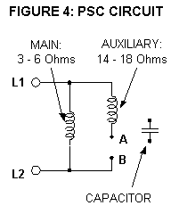
This is what I have always known as a PSC motor.
image_xvaovc.png

There is a run winding and there is a start winding with the capacitor.
The motor may be reversed by reversing either winding.
(I'm borrowing from capacitor start terminology and calling the winding with the capacitor the start winding.)
I have run across some special purpose PSC motors with two identical windings.
Either may the run winding and either may be the start winding.
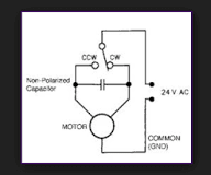
The advantage is that the motor may be reversed with a single pole double throw switch.
image_vg6j3t.png

There are indications that the motor under discussion is this type of motor.

Running a PSC on a VFD, don't you have to remove the capacitor and let the VFD develop the phase shift?
Don't the capacitive reactance and the inductive reactance shift in opposite directions when the frequency changes?
At 20 or 30 Hz that's gotta hurt performance.
Some PSCs can handle a 60Hz, 50 Hz shift with the same capacitor, some require a different value capacitor to shift between 50 Hz and 60 Hz.
More than a 20% frequency shift may not be good.

Bill
--------------------
"Why not the best?"
Jimmy Carter
 
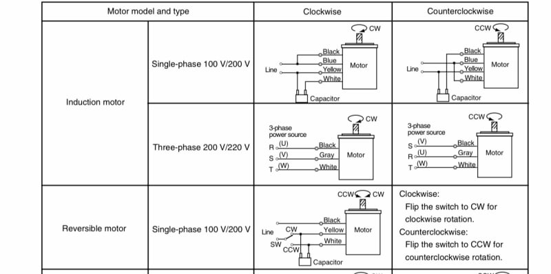
@waross Sir I can confirm your description of this motor. As you stated this is a reversible motor and the direction of rotation can be changed with a single switch(Attached the wiring diagram below)
2FEA6A34-A832-4310-A3D3-09B88A9AD9B7_k14n4d.jpg


Status
Not open for further replies.

Part and Inventory Search

Sponsor