More than one reply said:
Look at the specs; uF: 8 refers to an 8 microFarad capacitor.
VFDs don't like capacitors on the output.
Motor capacitors don't like a variable frequency.
Why not a single phase VFD?
That has been discussed more than once.
There are single phase VFDs that will run some types of single phase motors but not all types.
Many common single phase starting methods are ineffective at low frequencies.
Search this forum.
You can run a 'non-VFD' grade motor on a VFD as long as you are under loaded and don't vary the speed too much.
And you usually need to add additional cooling as well.
Inverter grade windings are better able to withstand the high frequency/high voltage stresses generated by the interaction of the steep wavefront of a PWM supply. This effect is not influenced by loading.
If you don't vary the the speed too much
from the rated speed, you generally don't need additional cooling.
Note that this motor may not be suitable for continuous operation.
I have not done this and i have never heard of this being done, but theoretically, this type of single phase motor actually has the best chance of all types of single phase motor to operate from a three phase VFD.
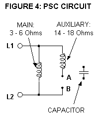
From the specs I infer that this is a type of motor which has two identical windings that are connected in open delta. The capacitor develops the needed phase shift.
But, that said, there are caveats:
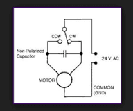
The capacitor would be removed before running from a three phase VFD.
The phase displacement between the windings is fixed by the physical location of the windings in the stator.
For a three phase motor the displacement is 120 electrical degrees.
For a single phase motor the displacement is 90 electrical degrees.
In this type of motor the angular displacement is unknown.
It is possible that the designer chose an angle of 60 degrees (the compliment of 120 degrees), however we don't know.
What are the implications of the physical, electrical angle between the windings?
An induction motor generates a back EMF. The phase angles of the back EMF are determined by the physical angular displacement of the windings.
If a supply with a phase displacement of 120 degrees is applied to a motor with a back EMF developed at a displacement of 90 degrees, you may expect circulating currents, but maybe not.
The circulating currents in both the rotor and the stator may be greater than rated full load current.
You may use reactors in the motor leads to reduce the negative effects of the PWM waveform.
That said, I don't have very high hopes that the theoretically possible will be satisfactory in real life.
This is an intermittent duty motor to start with.
You don't have much thermal reserve to play with.
Bill
--------------------
"Why not the best?"
Jimmy Carter
")
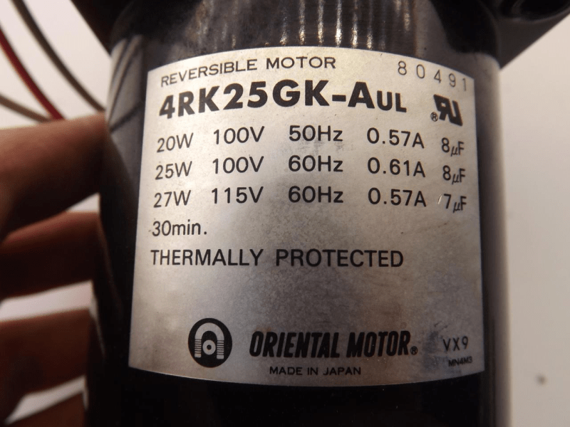
![[smile]](/data/assets/smilies/smile.gif "[smile] [smile]") . We are currently using this motor for a project which requires this motor to run at a lower speed. This motor comes equipped with a gearbox (Model: 4GK25K) but the speed still is very high. I was hoping for a simple mechanism to control AC motor speed with a dimmer switch, since there were youtube videos that showed it was possible (Source:
. We are currently using this motor for a project which requires this motor to run at a lower speed. This motor comes equipped with a gearbox (Model: 4GK25K) but the speed still is very high. I was hoping for a simple mechanism to control AC motor speed with a dimmer switch, since there were youtube videos that showed it was possible (Source: