Eng-Tips is the largest engineering community on the Internet

Intelligent Work Forums for Engineering Professionals

Splice Connection Check

Status
Not open for further replies.

Aytacoglu

Civil/Environmental
Dec 4, 2023
33
0
0
GB
Hi All,

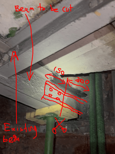
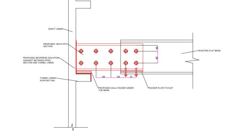
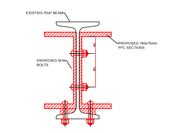
I need to check a connection for a steel beam that will be cut at its end (300mm from the edge). New beam will be installed which will be back to back channel sections (180x75PFC). These are going to be spliced together at the web and bottom flange (top flange splice avoided due to site clashes).

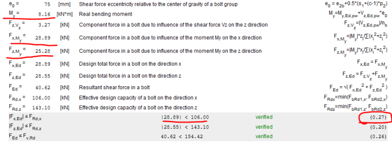
I want to check the connection to ensure this will work. Can anyone please assist me on how to go with this? Is it the case that the main design check will be with the bolts connected at the web which needs to be checked against the shear plus the additional force exerted by the bending moment?

I attached the details below:


Splice_1_dwb9y9.png


Splice_2_pvebpl.png


Thanks
 
Replies continue below

Recommended for you

What are the 6 bolts for? Is there a spacer between the channels? It's better to have the 6 bolts on the existing S Section. Why the bolts holding the neoprene? Adhesive? Can you use M20/M19 in lieu of M16? They have a lot greater shear capacity.

It's a simple shear and moment connection with the shear equal to the S Section reaction and the moment arm equal to the distance from the bolt centroid to the support 'block'.
No rocket science, if I read it correctly.


-----*****-----
So strange to see the singularity approaching while the entire planet is rapidly turning into a hellscape. -John Coates

-Dik
 
HI Dik,

Thank you for your response. When the back to back channels move off from the existing beam, there will be a gap between them which needs to be filled with a ~8mm plate to act as the "web". Hence the requirement for those bolts. I know that 6no. bolts are excessive and over design but I just wanted to keep it consistent with the right side for contractor to not get confused with it. The neoprene will be just attached to the tunnel lining and it has nothing to do with the connections.
 

Then why is it there? I don't see the purpose. Better to leave a 1/4" 'air' gap?

The real connection is to the S Section and it is likely better to use 6 bolts; You have to develop the shear and likely a significant moment for the eccentric load.

-----*****-----
So strange to see the singularity approaching while the entire planet is rapidly turning into a hellscape. -John Coates

-Dik
 
Hi Dik,

The neoprene is there to avoid bi-metallic corrosion due to cast iron rings touch the proposed steel. This was one of the requirements from the client.

In terms of the bolt requirement, I proposed 4no. M16's as the Bending moments we have at that location is 7.18kNm and the Shear Force is 13.09kN which I believe should be easily manageable by those 4no. bolts. But again, I still need to do the calcs to make sure about this.

I think the main check will be the force converted from the 7.18kNm moment which will be converted into a force from the moment arm. Am I correct in assuming this?
 
Hi SWComposites,

This is true for a connection which is required to carry higher forces. But when considering having such a low moment and shear force, don't you think this would be sufficient?

Splice_3_ngbgdx.png
 
I assume that this is the same connection as in your other thread? If so I agree with Tomfh that you should extend the plate further into the existing beam. Even if the loads work out that you need very few bolts, you are apt to have rotation that may cause a noticeable kink with a small plate with few bolts. It's just better to avoid that possibility so I would go longer on the plate and add more rows of bolts (perhaps even slip critical).
 

If a client requirement then you should leave it, for liability purposes... air gap accomplishes pretty much the same thing without trapping any 'water'.

The real connection is attaching the channels to the S Section. Does the connection have to be 'slip critical'? If so, the shear capacity is greatly reduced; this requires more bolts.

-----*****-----
So strange to see the singularity approaching while the entire planet is rapidly turning into a hellscape. -John Coates

-Dik
 
SWC... concur...

-----*****-----
So strange to see the singularity approaching while the entire planet is rapidly turning into a hellscape. -John Coates

-Dik
 
The issue I am having here which is not shown on the drawing is that there is another beam connected to the existing which is restricting the length of that splice section. Please note that the splice is not a plate and it is back to back angles connected to the existing, and it is only 300mm off the edge of the tunnel lining. That is the reason I am limiting the extent of the splice to only 150mm and providing 2no. rows of bolts.

Splice_4_kfcskh.png
 
Aw, I see. In this case I would weld. Making bolt holes with 1/16" tolerance in the field where you have so many encumbrances is going to be a real challenge, and quite costly. Bringing a welder in for a half day is nothing for something like this.
 
Unfortunately, I am in London and the client does not want any welding on site (this is a cable shaft and they consider welding to be a huge site hazard).. Usually in the UK welding is barely allowed on sites..
 
I would think that for this moment connection that it would be advisable.

-----*****-----
So strange to see the singularity approaching while the entire planet is rapidly turning into a hellscape. -John Coates

-Dik
 
I’m a long time aircraft structures stress analyst. Have designed lots of splice joints.
Regardless of the loads, I would make the overlap to the existing beam as long as possible, to give the longest force couple length to transfer any moments. I see no reason to skimp on this joint and save a couple of fasteners.
 
Status
Not open for further replies.
Back
Top