Continue to Site

Eng-Tips is the largest engineering community on the Internet

Intelligent Work Forums for Engineering Professionals

  • Congratulations cowski on being selected by the Eng-Tips community for having the most helpful posts in the forums last week. Way to Go!

Spliced Beam Reactions 1

Status
Not open for further replies.

Trillers

Civil/Environmental
Feb 14, 2011
66
Greetings:

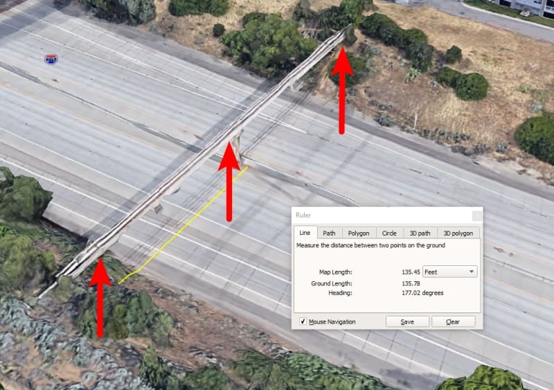
I am designing a steel beam to support a 16" waterline crossing over a creek. The waterline will be supported by the I-Beam by hangers at 8' OC which I analyzed both ways - point loads and uniform load. The clear span is 72 ft. Because of limited space the contractor can only bring in a maximum 40' length beam so bolted splices will be required. I do not want to use a welded splice as I am not confident that the contractor's welder, although certified can provide the welds we need.

The bolted splices will carry 75% of the beam capacity as per my design. These splices are located at the 1/3 points from each end so the sections between supports are 16'-40'-16'. This was to avoid a splice at the mid-point of the spliced beam. In designing this beam I assumed that the splices can be considered as supports so that the max span under consideration is the middle 40' with the 16' sections at each end.

I referred to AISC Appendix J and the FHWA splice manual. My in-house peer reviewer says he does not believe my assumption is correct, but he does admit he has never designed or been involved in anything like this. I've designed for bridges and structures but never a waterline support, although I believe the principles are the same. Now he has me wondering if my assumption is correct.

Was hoping you structural gurus could chime in? Would hate to have a watermain rupture because of wrong assumptions!!

Thanks!!
 
Replies continue below

Recommended for you

Sorry about the absence folks....not been abducted although some swear that UFO sightings are definitely on the rise in our region. Delay in responding is due to being out of office and the time zone difference.

Anyway I guess my post definitely confused a lot of you.

To clarify on Ingenuity's point - the clear span is 72', the 16-40-16 indicates the points at which I intend to utilize bolted splices to create in effect a continuous beam 72' long. I've attached a couple of drawings and a sketch which should help clarify things. I may have confused all with the description I gave. Essentially the pipe is buried until it reaches the pedestal footing at which point it crosses the creek with a clear span of 72' then down to the pedestal across the creek where it is underground again. The phamENG sketch is very close except that beyond the 16' points (end supports for the beam) the pipe is buried as shown in the first attachment.

In the second attachment you can see the original design which required a clear span of only 47 feet to be supported on the bridge superstructure. Then we were directed to avoid hanging the crossing section of pipe on the bridge. Additionally we were directed to widen the clear span so that the beam pedestals would be outside the line of the bridge, thus the 72' span. You can see this in the bottom part of the drawing at the detail marked "PROPOSED." For simplicity I am not showing the web stiffeners along the beam.

Hope this helps - I look forward to additional guidance, recommendations and critiques.

 
 https://files.engineering.com/getfile.aspx?folder=5ded3a4f-1ac8-481b-8b02-655287a727d0&file=Scan-Combined.pdf
You will need a lot of stiffness in the transverse direction. I suggest to use double girder with pipe support/maintenance platform, or a 3D truss. Is the 4' freeboard adequate?
 
All this still begs the question on how would you imagine that a splice functions as a 'support' in this context. Everything you have shown shows a 72ft simply supported span. You can't just add a splice and call it a support.
 
Ok, so single span of 72' with 2 splice locations for construction...but:

pipewf_aygx0s.png


Is this a W12x65?

You use the singular wording of I-beam, so that implies a single W12.

The self weight deflection ONLY for a W12x65 for a 72 foot span is 2.5" at midspan!

Span-to-depth (L/D) = 72!

You cannot span a single W12 for 72' with an unbraced length of 72'.

EDIT: With a Lb >> Lr = 35.1' you are well into the domain of elastic LTB...your water pipe may be in the creek!
 
Why is this not being designed by a structural engineer?

Your design assumptions and proposals are horribly wrong here and as far as I can see lateral torsional buckling has not been considered (web stiffeners wont fix this..) deflection has not been considered, snow/maintenance/accidental (kids using it as a bridge) loadings have all presumably not been considered since the beam under its own self weight alone deflects excessively.

Once the beam is in place, how do you hang the pipe? Surely you need a construction access load?

I don’t wish to sound harsh but this proposal is miles off the mark and may well land you in a lot of trouble when it goes wrong.

A starting point would be a triangular or box truss.


The pipe is 16" waterline in original thread and supported by the hangers. However , the line is 6'' on the last released dwg. For an experienced eye,it is not a magic to say that , the proposed beam W 12 X 65 is not suitable.

The 2X 45 degr DI bends will exert an upward force ( 22.5 degr. with vertical). The bends shall be connected to the concrete abutment with pipe clamps.

My suggestion will be, consult an experienced structural engineer familiar with type of jobs.
 
As noted above, this beam need to be stiff enough to not impart undue stress on the pipe. It also must be stable for the long expanse you have. Either two beams (likely 30+" deep) tied together with diaphragms, or some sort of box truss will be required to support this pipe. Also remember to consider thermal loads - I'm guessing the hangers have some sliding capability to them.
 
I'd be curious to know what deflection a W12 would have on that span... I'd be thinking a W21 or maybe W24... If you fix it at the ends, it could become a catenary.

Dik
 
that pic shows two splices, but not symmetrical ? Since both splices point to the same detail, it'll need to be designed for the loads nearer the CL.

fixing at the ends would obviously help (it'll 1/2reduce the moment in the beam.

I like retired's idea of using a small truss beam.


another day in paradise, or is paradise one day closer ?
 
Trillers,

Your design is critical in weak axis bending. For unbraced length of 72ft, and a slenderness ratio of 200, ry=72*12/200 = 4.32 in3. This leaves you with the choice a rolled shape W14x398 and above, but then, the beam weight is almost double of the estimated beam load 330 plf. The break down of the estimated load is as below:

Wwater = 87 plf
Wpipe = 83 plf (sch 40)
Wice = 70 plf (td = 3")
W = 87+83+70 = 240 plf

Try W14x398, Ix = 6000 in4, Sx = 656 in3, Wdgn= 240+400 = 640 plf
- Stress check
M=0.125*0.64*722*12=4977 "-k
f = 4977/656=7.6 ksi, ok

- Check deflection
Δ=5*0.64*724*123/(384*29000*6000)=2.22", a span ratio of L/389, ok

Oh, well....!


This is going to have to be a double wide flange laced together with plan bracing and pipe 'saddles' which act as diaphragms to brace the top flange (in a way). That eliminates LTB issues and weak axis bending issues.

There are loads of these types of pipe bridges in the Salt Lake City area. Spans are probably 150ft or more over a 8 lane interstate with a support in the center.

pipe_bridge_over_215_3_pzfux0.jpg


pipe_bridge_over_215_2_w3qzvh.jpg
 
Not in my experience Steve, i expect someone just went for a full capacity splice?
 
For single beam solution, you can go down to W14x283, with 1"x20" cover plate at top and bottom.

image_xakwuc.png
 
Gentlemen:. Thanks all for the insight and wisdom. I will now go back to the drawing board bruised but wiseR.


Status
Not open for further replies.

Part and Inventory Search

Sponsor