Continue to Site

Eng-Tips is the largest engineering community on the Internet

Intelligent Work Forums for Engineering Professionals

  • Congratulations waross on being selected by the Eng-Tips community for having the most helpful posts in the forums last week. Way to Go!

Split bases of weld on pad-eyes/lifting lugs - Why? 11

Status
Not open for further replies.

Nereth1

Mechanical
Feb 2, 2014
136
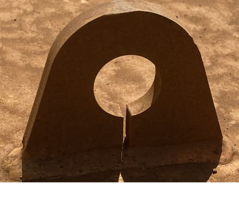
For mostly curiosity, but at this stage also the preservation of sanity, there is an ongoing discussion in our office on why we see weld on pad eyes/lifting lugs with splits in them. See image below:
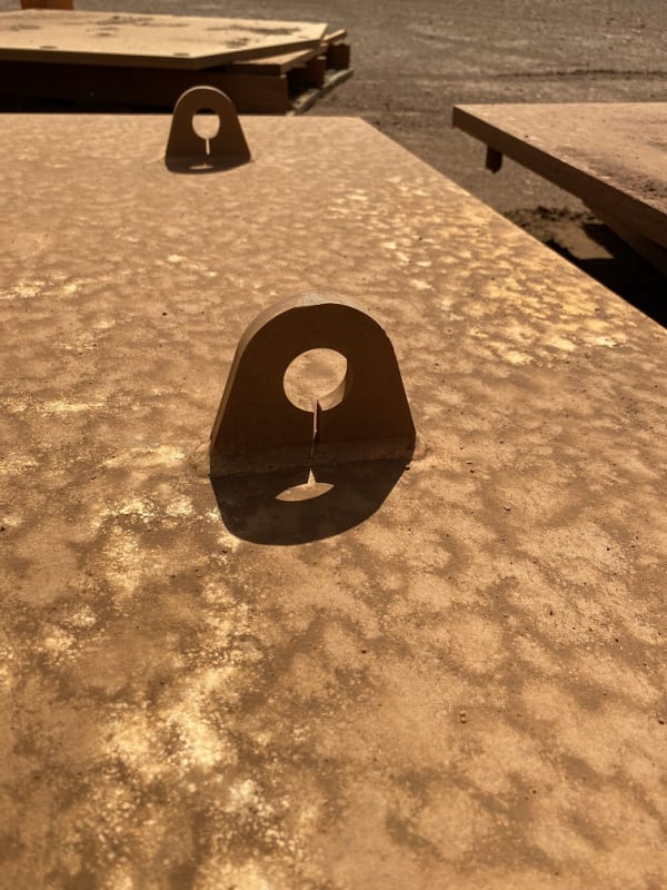
Split_pad_eye_tfwlb6.jpg


We can speculate some minor decrease in certain stresses (e.g. contact stress reduction as it will more easily flex to conform to slightly lower radius of the pin inside it), but at the cost of large stress increases in other areas (bending stress in the eye, peak fatigue stress concentration for any longitudinal stresses in the plate to which it is welded to). It doesn't seem easier to weld (if anything it seems more difficult), and it doesn't seem cheaper to manufacture.

So we are generally at a loss.

My best guess is someone drew this 40 years ago by hand, sneezed near the end of the drawing process, left a line on the drawing, and went "Well, not drawing that again. Guess it's a feature now." and it never got corrected.

But realistically it's across multiple client sites, vendors, and industries. It's not common, but it exists everywhere. So there must be some reason this exists.

Can anyone try to illuminate me a little on this one?
 
Replies continue below

Recommended for you

To mitigate impact forces there needs to be significant deformation, preferably elastic deformation - the slot won't make a noticeable difference in the amount of deformation vs the deformation of all other items in the lifting system.
 
dik - in those cases it's often a "fuse" element and are oriented parallel to the most likely direction of vehicle traffic. You want the sign/lightpole/whatever to stand up to wind loads, but if it's in the right-of-way or reasonably close to it, you want it fail rapidly in shear during a collision. Flexural failure can create a ramp for the vehicle, and no failure at all can cut a car (and it's occupants) in half.
 
They have frangible connections below the anchor rods to allow shear failure... an annular V cut in the connection.

Rather than think climate change and the corona virus as science, think of it as the wrath of God. Feel any better?

-Dik
 
There could be more than one reason to provide the gap, I am more on the side of stress concentration and distribution argument/concerns. As the gap certainly would alter the structural properties of the pad eye, including geometry and shear centers, the load paths and reactions have changed as well.
 
dik - sorry, thought that was what you were talking about. Beats me, then.
 
The cuts in Electric baseplates are for drainage. They nut both sides of the plate and stand the plates off with no grout. I believe only Sparky's do this.
 

JStephen explained the cutting process , I assume with his practice ( based on oxygen burning or plasma cutting ) . These type of holes drilled or laser punched in our region. There is a useful instrument google. You may write thick plate laser cutting and search the web to see the process . Please look again to the hole surfaces for both cases..although the pictures are not high resolution, IMO,apparently laser cut.


Instead of estimation, you may perform a simple calculation to see the difference. Bending stiffness for one leg , four times the slotted double legs and the impact force 20 % more for the single leg case. The slotting will substantially reduce the bending and shear stresses at legs and fillet welding.

 
Hi all,

Detail photo below FYI. Definitely laser cut. I can blow it up even higher res if required!

Detail_photo_of09mc.jpg
 
HTURKAK said:
There is a useful instrument google. You may write thick plate laser cutting and search the web to see the process
Thanks, I'm sitting 100ft away from a laser plate machine and two plasma tables. Piercing is an issue for all of them - it takes more time! Here is a great video showing how much more time it takes (found via that useful instrument, google):
If a manufacturer can increase the output of their plate machines by decreasing the amount of piercing rather than having to add another machine, that is going to be the path they take.


There have only ever been a few references I have ever seen used or applied for designing lifting lugs (which seems to come up once or twice a year on this site) - none of which have anything like the split we are talking about as part of the design. If something like this exists I would happily be proved wrong. Without that, it seems the only practical explanation for the split is to help on the fabrication side.
 
dauwerda,

I believe a FEM program is closely available to you too. Can you run the models and check the results?
 
It's too wide for a laser cut-in kerf. It has to be a deliberate, designed feature. Piercing with a laser or water jet is child's play for material this thin. I don't see how it makes water induced corrosion better - seems worse to me because water will sit there. I don't see how it makes strength better - the weld passes will undercut at the slot. Overall, it looks like more work in the shop so there should be a good rason for it, which I have not read yet..
 
I was suggesting it could drain water from damaging the pin, hidden by the shackle, were one to use it for a permanent installation. As I wrote before, that's a pretty weak guess.
 
Back in the day when cutting torch was the only option you only needed slots like this. It would take longer to burn through a piece of 2" steel than to cut then entire shape. I'll bet that these are carryovers.
I have some artwork created by guys in the Long Beach shipyard ca 1944. Some of them have slender 2" long pointed features cut from 4" plate, by hand.

= = = = = = = = = = = = = = = = = = = =
P.E. Metallurgy, consulting work welcomed
 
One of the shops I use a lot has a water jet that cuts 5" steel with ease.
 
Yeah I would buy the "Carryover" design explanation - Suspect no one remembers why these exist thus no one has the confidence to eliminate them.

We can't ask "the" fabricators because these are across multiple fabricators, industries, and countries. Not one fabricator.

I have seen these (although can't find photos), where the split looks like 10mm+
 
Nereth1 said:
Suspect no one remembers why these exist thus no one has the confidence to eliminate them.

Yeah, well it's entirely possible they are using the same equipment as when they started :)

Regards,

Mike


The problem with sloppy work is that the supply FAR EXCEEDS the demand
 
Nereth1,

We have provided all the possibilities with summeries above. I do not understand why you are still questioning the finding. From the first post I thought that you know what you are talking about. Now I started having suspicion on that.

In the pin connection analysis you will see some significant stresses but these are not near enough the stresses occur on the contact side. The stresses in the area before the split is also positively contributing stress to the pin connection and these stresses do not reach the welds if you size the height adequately.

The split eliminates this stress, and therefore weaken the pin connection in several ways.

Of course there are other contributors on the higher stresses in the pin connections. The most effective is the diametral gap between hole and pin. The smaller the gap the lesser stresses. I do not want to go further, ı trust all clear now.
 
I'm highly skeptical that this padeye cut was a design element. This looks to be a field standard padeye that is commonly used in large fab yards for general handling. I tend to lean towards this cut being performed by direction of construction personnel for efficiency of cutting table torch.
 
Hi all,

The implication that this somehow solves some stress issues, and my inability to intuit my way through that (the explanation is very unclear to me), led to some comparative FEAs I wanted to share with you (which mostly confirm that this does not really help anything). Let me walk you all through it. First, test setup:

1) Two rows of lugs. Front row of lugs vertically loaded. Back row of lugs loaded at 45° from vertical. Sum of loads the same.
2) LHS solid, RHS with split. Otherwise identical.
3) Pins are 29.5mm, holes are 30mm. Contact is modeled as frictional with Mu=0.2
4) Edges and bases of plates are fixed.
5) Mesh is quadratic, material is fully elastic. Mesh density as shown.

FEA_Setup_wpyqwu.jpg


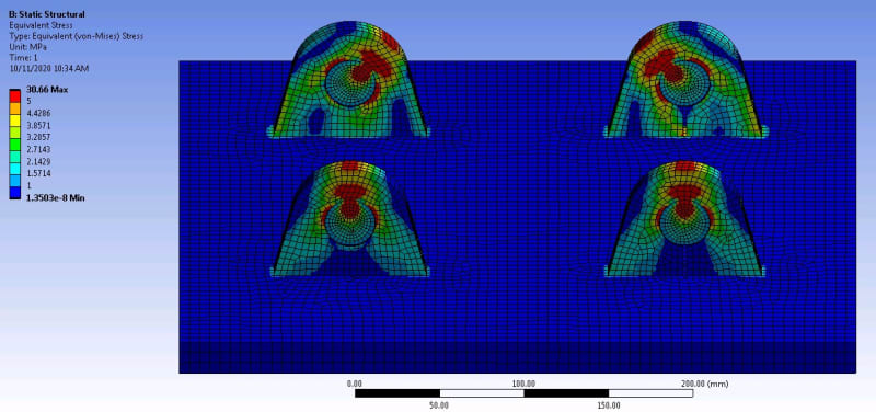
Overall idea of equivalent stresses below:

FEA_Von_mises_overall_e7ygkw.jpg


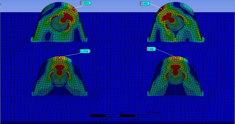
External splitting stress. Makes a very small difference but favours non-split lug. The peak is higher and the size of the hotspot is higher, in the split lug.

FEA_External_splitting_stress_vzr8xw.jpg


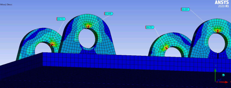
Internal contact stress. Makes very little difference in vertical pull. Split is noticeably detrimental to 45° pull.

FEA_Internal_splitting_spob4p.jpg


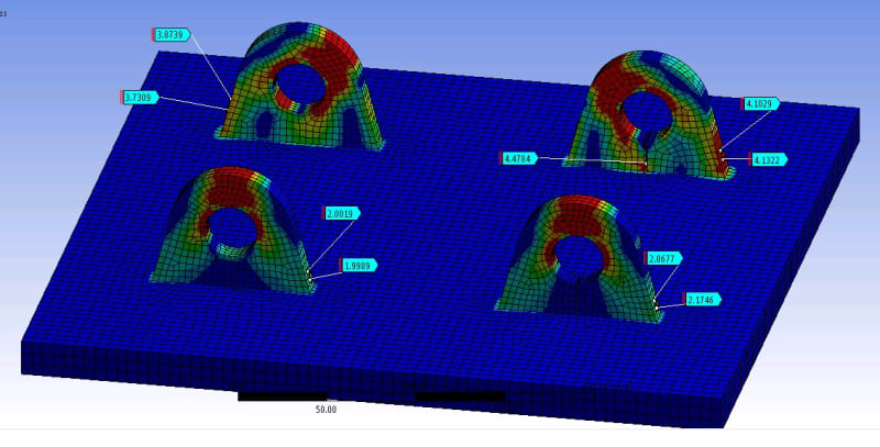
Peak stresses near the weld - I think this is the crux of the issue. Or rather the reason not to split the lugs. Slightly higher stress on the straight pull. 10% higher stress in the angled pull on the split lug. A hotzone introduced with 15% higher stresses in the angled pull on the split lug.

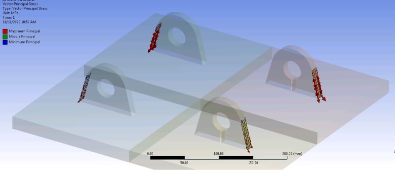
I have also included below a set of vector principle stresses on the high stressed surfaces near the weld, to show that these stresses are in a direction that flows through, and pulls on, the weld. So they are relevant to weld stress.

FEA_Stress_near_base_tjlkux.jpg


FEA_Stress_near_base_DIRECTIONS_kbdm0o.jpg


I would conclude that I can't see how this split could be done for reasons of stress reduction. But happy to carry out some further analysis-on-demand now the model is setup, if anyone has some interesting items to check.
 
Status
Not open for further replies.

Part and Inventory Search

Sponsor