Continue to Site

Eng-Tips is the largest engineering community on the Internet

Intelligent Work Forums for Engineering Professionals

  • Congratulations KootK on being selected by the Eng-Tips community for having the most helpful posts in the forums last week. Way to Go!

Split bases of weld on pad-eyes/lifting lugs - Why? 11

Status
Not open for further replies.

Nereth1

Mechanical
Feb 2, 2014
136
For mostly curiosity, but at this stage also the preservation of sanity, there is an ongoing discussion in our office on why we see weld on pad eyes/lifting lugs with splits in them. See image below:
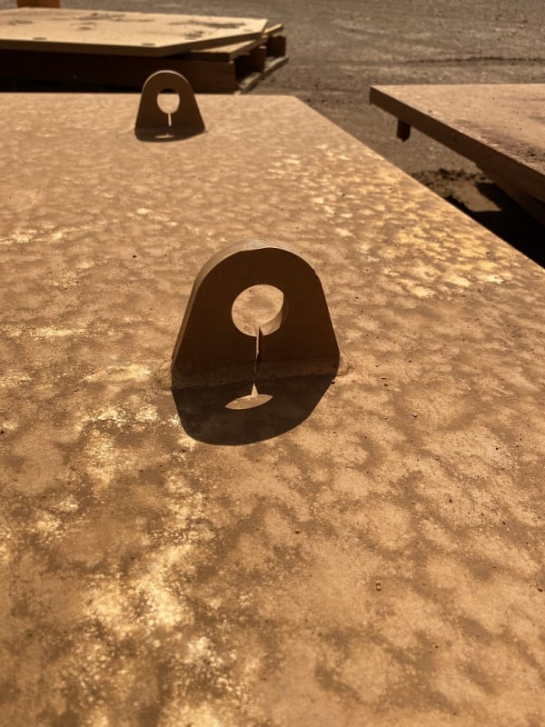
Split_pad_eye_tfwlb6.jpg


We can speculate some minor decrease in certain stresses (e.g. contact stress reduction as it will more easily flex to conform to slightly lower radius of the pin inside it), but at the cost of large stress increases in other areas (bending stress in the eye, peak fatigue stress concentration for any longitudinal stresses in the plate to which it is welded to). It doesn't seem easier to weld (if anything it seems more difficult), and it doesn't seem cheaper to manufacture.

So we are generally at a loss.

My best guess is someone drew this 40 years ago by hand, sneezed near the end of the drawing process, left a line on the drawing, and went "Well, not drawing that again. Guess it's a feature now." and it never got corrected.

But realistically it's across multiple client sites, vendors, and industries. It's not common, but it exists everywhere. So there must be some reason this exists.

Can anyone try to illuminate me a little on this one?
 
Replies continue below

Recommended for you

Impressive. Suggest to eliminate the left model, then fill the gap in the right hand model with elements to replace it. By doing so, you have two models with identical pattern for comparison. Also, can you display tension, compression and shear stress with +/- scale. Thanks.

image_st21a3.png
 
Nereth1: Great work, wish I could give you a handful of stars... what FEM program did you use?

Rather than think climate change and the corona virus as science, think of it as the wrath of God. Feel any better?

-Dik
 
Dear Nereth1 (Mechanical), nice work... will you pls look for the pins 20 mm, and loading horizontal? ..I remember the split lugs for horizontal ( lugs loaded at 90° from verticaI ) for permanent installation . In order to compare impact loading effects will you pls look to the deflections ( at contact point )?

A pink star to you for this great work...
 

I'd be a little concerned if the two models were radically different...

Rather than think climate change and the corona virus as science, think of it as the wrath of God. Feel any better?

-Dik
 
R13:

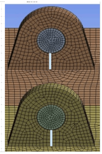
They are identical models already. I mirrored them across the centre plane then deleted out the strip under the hole. The plates are also restrained between lugs so that stresses cannot transfer between lugs.

dik:

ANSYS

HTURKAK:

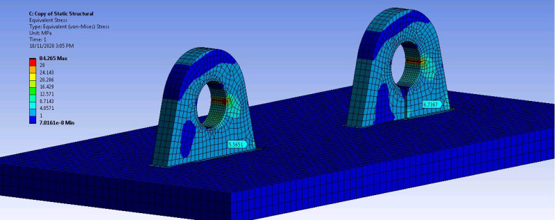
Pins 20mm, pulled horizontally. Tightened up mesh at contact point as results were getting discontinuous. Equivalent stress and deflection pictured below. I haven't put probes on the contact points because they're very sharp peaks, difficult to find equivalent points across the two. But looking at the ranges of stresses, they're very similar. The stresses at the base, however, are much higher on the split lug, likely because the stresses are introduced on the RHS, and have no stiff path towards the LHS for the LHS to do any real work to assist the RHS.

FEA_Side_pull_bjpfc0.jpg


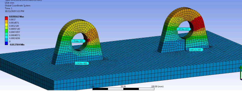
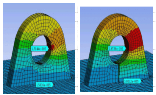
On deformation, there is a slight increase, on the order of 10%, however, the absolute value of the difference between the two designs, is around a tenth of a micron (at 1000N). These lugs, looking at the FEA, could probably take 10-50x the force, but assuming everything stays elastic, that's still just a few microns of deformation gained. This would almost certainly be negligible compared to whatever flex is in the chain, lifting kit, or the attached part. Any appreciable difference in energy absorption would have to happen in the plastic deformation range (and I'm running out of time today to run that analysis).

FEA_Deformation_kk7vh1.jpg
 
Nereth1,

Good work. Your finding with the analyses gives you presentations on my posts as far as I can see.
This proves that the split application is not for stress reduction, it is fabricator’s choise of manufacture.

You have used 0.5 mm of diametral gap for the connection. Can you achive this gap or lower gaps for all lifting?

Do you always use manufactured pins for lifting applications?

In case you use shackles for lifting what sort of gap do you consider?

Do you know the tolerance on the shackle pins to consider in the design?

Engineers have to satisfy themselves first. What you did is a start I would say.
 
Do not mean to be picky, but the mesh on the right is finer then the left. The differences are small, are exist.

image_ii31b6.png
 
Thanks for the ANSYS...

Rather than think climate change and the corona virus as science, think of it as the wrath of God. Feel any better?

-Dik
 
@R13

You're right ofcourse, but the chance that it changes the results enough to change the conclusion, is minimal, given how many (quadratic) elements are already there. Purely based off my judgement (not really worth a convergance analysis)

@Saplanti

Realistically the 20mm pin in 30mm hole in the second analysis, is basically a point load, and that scenario still showed no structural advantage to the split lug.
 
Status
Not open for further replies.

Part and Inventory Search

Sponsor