Eng-Tips is the largest engineering community on the Internet

Intelligent Work Forums for Engineering Professionals

Split Level Slab Analysis and Detailing

Status
Not open for further replies.

psychedomination

Structural
Jan 21, 2016
114
0
16
BM
Hi there,

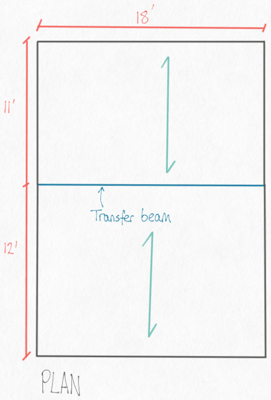
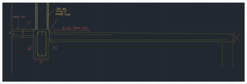
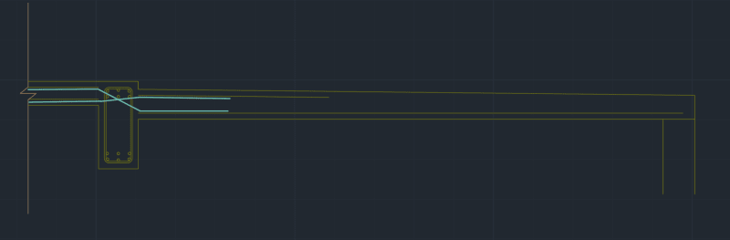
I'm working on a project, where I have designed a transfer beam that has slabs tying in to it at two different levels.

Dimensions are shown below :

Drawing_13_m1dp6h.png


I have a few questions.

1. Would you consider the beam to be a T beam when it has a split level of 2"? What would the cut off for when a stepped slab can and cannot be designed as a T beam? For simplicity, I designed the transfer beam as a normal rectangular beam, but I'm sure there must be some contribution from the slabs.

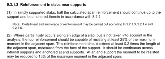
2. With the change in slab levels, should the slabs be designed as continuous or simply supported? What would the threshold for this be? (e.g. at a 6" step design as simply supported etc)? For context there are two slabs framing in to the transfer beam, both approximately 11' in length.

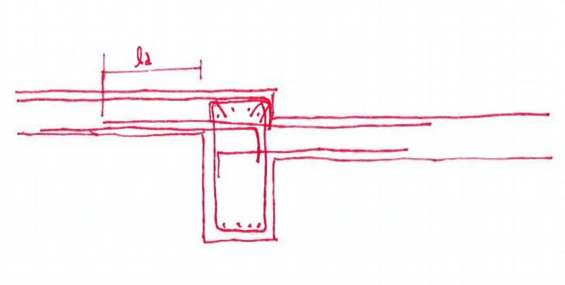
3. What would be the ideal detailing be for a situation like this?

A.
IMG_0327_sxeupx.png


B.
IMG_0329_do9z6f.png


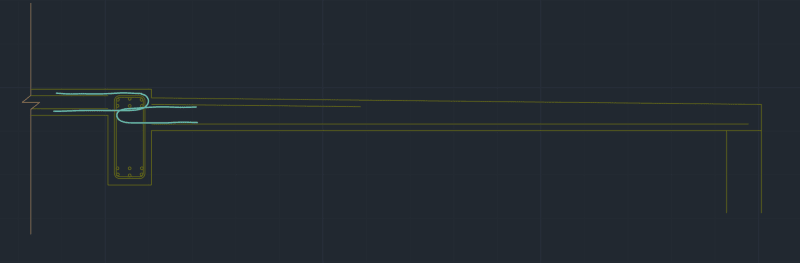
Or is there a better detail that you would be able to share for this interface?
 
Replies continue below

Recommended for you

When I do these, I generally consider the slab as an inverted L with the upper slab effective. I use the edge effective width limits just to be conservative. If the beam has a pretty heavy load on it, the compression zone could extend down into the lower slab. Its possible to consider this with either a hand calculation or a more robust analysis/design software. I wouldn't expect the difference in reinforcing required to be that different. Assuming that this is a new design, the amount of steel you are going to save with a more sophisticated analysis should be trivial.
If they are one-way slabs, I also don't consider continuity. I still put top steel in over the beam but I make sure I have the bottom steel in for an end span condition.
My preferred detailing for this is to hook the upper slab top bars in the beam and the bottom bars of both slabs in the beam. I extend the lower slab top bars through the beam and give a development length past the slab. See below.
DOC_27_osuezi.jpg
 
@RobertHale, Thank you very much your response is very helpful. Designing as an L beam seems reasonable to me and should be a more efficient way of designing the section (instead of a rectangular beam).

In reality I believe the slabs will act as two way slabs, however for simplicity with hand calcs, I designed them as one way (all load assumed in the shorter direction) see below :

Drawing_14_dd4a0s.png


I also provided minimum area of steel required for temperature/cracking as distribution bars in the long direction and included hogging reinforcement at the top near the support as per EC2 9.3.1.2(2). I used 25% of max bending moment as per EC2:

EC2_Exert_9.3.1.2_xjf4fn.png


In hindsight, I'm not sure if this is a suitable approach to try to "force" one way bending for a slab with a ratio of ~1.5 (less than one way allowance of 2), so I'll also check the slab as a two way panel with supports on 4 sides (not continuous) in TEDDs or something to make sure the cracking distribution bars specified are adequate.

You mention if "they are one-way slabs, I don't consider continuity". Would this differ if they are two-way?

I also note your detail, thank you for sharing that.

I appreciate your help so far.
 
When I design most two-way slabs, I use RAM Concept. I may check some of the slab lines with something like ADAPT PTRC, but my design will get flushed through Concept. With Concept, there isn't a way to force discontinuity over the beam. Now, if I am looking at a one-way system, I will generally just do an ADAPT slab run and an ADAPT beam run, so I get a lot more say in load distribution and boundary conditions.
 
Status
Not open for further replies.
Back
Top