Continue to Site

Eng-Tips is the largest engineering community on the Internet

Intelligent Work Forums for Engineering Professionals

  • Congratulations waross on being selected by the Eng-Tips community for having the most helpful posts in the forums last week. Way to Go!

spring value of continous vs simply supported beam 2

Status
Not open for further replies.

dccd

Civil/Environmental
Feb 19, 2021
150
We all know that the continuous beam is generally stiffer, hence , the interior support can attract a fair value of hogging moment.

I am playing around with the spring rotation value to limit the hogging moment reaction to certain amount (lower value compared to all fixed condition). However, I found that when the beam is in continuous , the amount of spring value that required to achieve certain amount of reaction moment at support is lower. Is it wrong ? Why ?

Can someone help to explain it ? Say that when in all fixed condition, the reaction moment at interior support is 300kNm, but I want to limit it to 100kNm only. Hence, I adjust the spring value to achieve it. In single span fixed fixed condition, the spring value is 100kNm /deg , but in continuous fixed-fixed-fixed condition, the spring value is 50kNm /deg. Why ?
 
Replies continue below

Recommended for you

Post some diagrams. It's a bit hard to visualise your question.
 

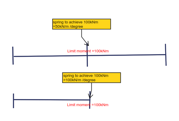
Here's the simple sketch for your understanding. Imagine that the interior support can take up to 300kNm, while for single span fixed fixed condition, it can take only 150kNm, my interest is to limit all the hogging moment to lower value (say 100kNm), so i adjusted the spring value. I found that the amount of spring value that required to achieve certain amount of reaction moment at support for continuous beam is lower.... Why ?


00013_cdkwhv.png
 
I don’t understand your question sorry. What do you mean by “can take up to 300kNm”, etc.

And if this is a symmetric continuous beam there shouldn’t be any rotation at centre support, so why is spring of support relevant?
 
How are you loading these beams?

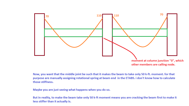
When you say reaction moment, do you mean the node reaction, or the bending moment in the beam's left span? The latter is the sum of the node reaction and right-span moment. Please post your moment diagrams.
 

I suspect you are in a confusion.. let me express ;

Suppose that you have a two span,with three supports continuous beam , and you have the chance to sift the location of middle support and the other supports are fixed;

The fixed end moment at mid support may develop say for the first span ,if one of the following conditions are provided,

i- The beam is uniform, the support at mid point and loading is symmetric ,so the rotation is zero at midspan ,

ii- The second span is loaded with a different load to get the rotation is zero at midspan,

iii- The stiffness of the second span can be changed together with span loadings again to get zero rotation at mid support..

Can the mid support moment for the first span be higher than fixed end moment?

The answer is yes... i will suggest you to look the moment distribution method ( CROSS ) to get the concept..
 
steveh49 said:
When you say reaction moment, do you mean the node reaction,

Yes, reaction moment means the node reaction , means reaction at the interior support for continuous beam and the end moment for single span fixed-fixed end beam...
 

I am playing around of the stiffness of support to see the difference ... Bascially, I want to know the difference between the simply supported /continuous beam and the spring value/ reaction moment at the support
 
For the continuous beam case, the left span bending moment and the support reaction aren't equal. Take care to use the terms properly.


In the continuous beam case, at the central support:

Left span bending moment + right span bending moment + node reaction = zero

It sounds like you're loading the left span only but you didn't say. In that case, the left span bending moment at the support would be equal (and opposite) to the sum of the node reaction and the right span moment. So the node reaction would be less than in the single span case, so a lower node stiffness needed.
 
steveh49 said:
In that case, the left span bending moment at the support would be equal (and opposite) to the sum of the node reaction and the right span moment. So the node reaction would be less than in the single span case, so a lower node stiffness needed.

Can you explain why ? The node reaction for continuous case would be less than in the single span case ? Node reaction here refers to support reaction ? Or moment ?

As I undertsand, for continuous case, (even loaded in 1 span only), the interior support will have the maximum support reaction and max moment , why node reaction would be less than in the single span case for continuous case ?
 
Your middle support cannot be fixed otherwise your continuous beam is over constrained.

As noted in your other thread a rotational spring stiffness is set such that at a specific moment the joint rotation is unity. Doing as you are, assigning a false joint stiffness to satisfy an arbitrary max moment, can be potentially unsafe for member or connection design.

My Personal Open Source Structural Applications:

Open Source Structural GitHub Group:
 
Celt83 said:
As noted in your other thread a rotational spring stiffness is set such that at a specific moment the joint rotation is unity

This means the joint is fully rigid ? fixed condition ?


I am playing around the value of spring to change the max moment over support so that I can reduce the reinforcement in the beam/column joint.... I am assigning some sort of release to the joint to reduce the support moment abit
 
I thought this was just a learning exercise but now it sounds like a real concrete design. In your first post, you mentioned reducing 300 kNm to 100 kNm. That's too much redistribution. If you get 300 kNm with true stiffness values, you can't go below about 240 kNm after redistribution. Check your code of practice for the actual limits that apply to you.


It's just practice, the value doesn't matter, I just want to get clear concept about the relationship of spring, continuous /discontinuous beam.... I am aware there's too much distribution.... Just forget abut the code. I just want to know why when the beam is continuous, the spring value required to achieve certain lower value of reaction moment is lower....
 
The node rotational spring stiffness is lower for the continuous beam because the second span also has a stiffness that contributes.

Single span node stiffness = continuous beam node stiffness + stiffness of second span.
 
dccd,

how about you upload a screenshot of your model showing:
- member sizes
- locations of the springs you are talking about
- node fixity settings
- loading
- shear, moment, slope, and deflection diagrams

That should show us exactly what your trying to do and we can all speak better about it, as right now I think some things are getting lost in just text explanation only.

My Personal Open Source Structural Applications:

Open Source Structural GitHub Group:


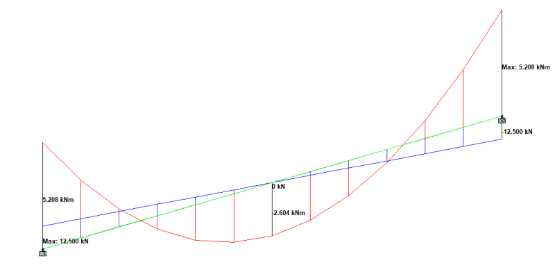
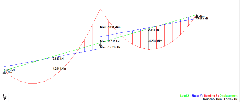
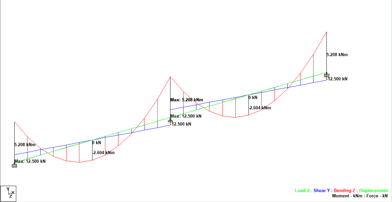
My actual model is more complicated than the exampel posted below. To simpligy things, I have model 3 beams below, one with single span beam subjected to UDL , another two are continuous beam subjected to UDL ..
I was trying to model this situation out ( with all 3 fixed condition) , but it seems that I cant do it in Staadpro . I have no idea why I am not able to model fixed fixed fixed beam ..
However, I tried to model in 3 situation
a.)fixed fixed
b.) pinned pinned pinned
c.) fixed pinned fixed

Surpisingly, fixed fixed pinned acting like fixed fixed , with no chnages in reaction and moment ...

0022_aosxws.png


0021_h9spnc.png


0024-fixed_fixed_pinned_behupe.png
 
I wonder why the loading is different ?

The first (single span beam) has 25kN applied, the 2nd and the 3rd seem to have 50kN applied ?

The 2nd doesn't look like "pinned pinned pinned", the 3rd doesn't look like "fixed pinned fixed" ... that'd imply zero moment at the mid support ?
2nd and 3rd show the difference between pinned and fixed supports with a continuous beam.

To get 2 SS spans you need two nodes at the mid support.

another day in paradise, or is paradise one day closer ?
 
Status
Not open for further replies.

Part and Inventory Search

Sponsor