Continue to Site

Eng-Tips is the largest engineering community on the Internet

Intelligent Work Forums for Engineering Professionals

  • Congratulations waross on being selected by the Eng-Tips community for having the most helpful posts in the forums last week. Way to Go!

spring value of continous vs simply supported beam 2

Status
Not open for further replies.

dccd

Civil/Environmental
Feb 19, 2021
150
We all know that the continuous beam is generally stiffer, hence , the interior support can attract a fair value of hogging moment.

I am playing around with the spring rotation value to limit the hogging moment reaction to certain amount (lower value compared to all fixed condition). However, I found that when the beam is in continuous , the amount of spring value that required to achieve certain amount of reaction moment at support is lower. Is it wrong ? Why ?

Can someone help to explain it ? Say that when in all fixed condition, the reaction moment at interior support is 300kNm, but I want to limit it to 100kNm only. Hence, I adjust the spring value to achieve it. In single span fixed fixed condition, the spring value is 100kNm /deg , but in continuous fixed-fixed-fixed condition, the spring value is 50kNm /deg. Why ?
 
Replies continue below

Recommended for you

Code:

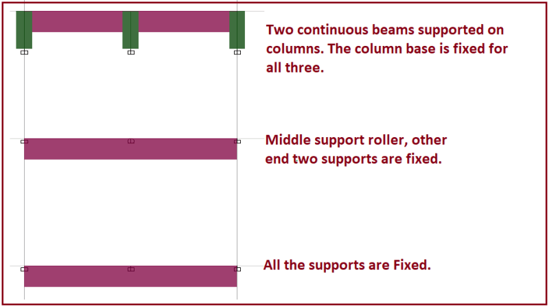
huh ? The beam is each 2.5m each span , subjected to UDL of 10kN/m ...
 
rb1957 said:
To get 2 SS spans you need two nodes at the mid support.

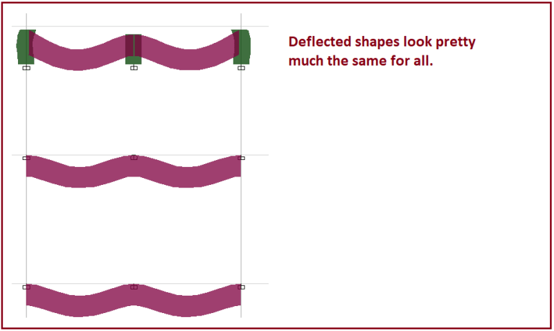
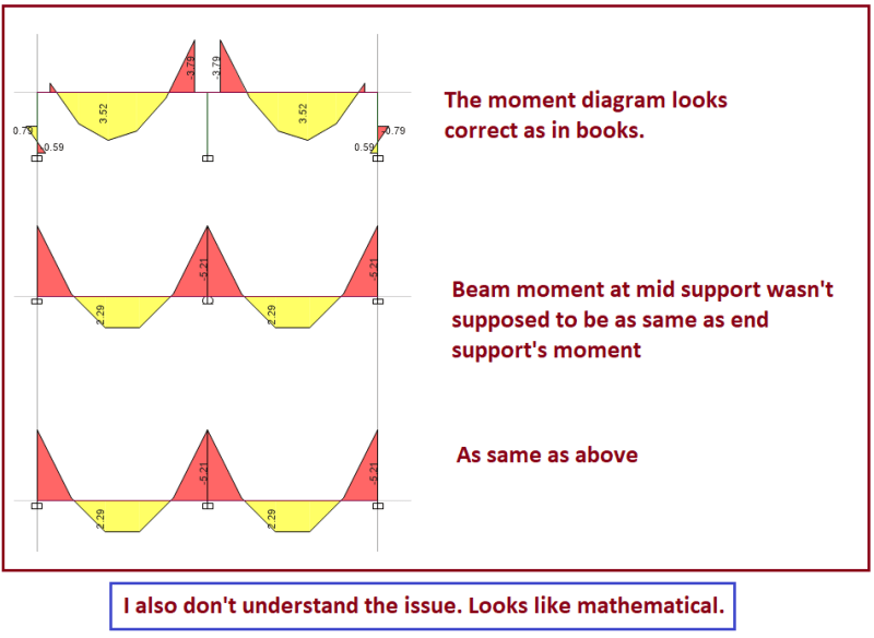
Suprsingly, 3rd one looks like 2 SS beam albeit I have assigned the support to be fixed pinned fixed for the continuous beam.
 
" I have no idea why I am not able to model fixed fixed fixed beam ." because that over constrains the model, you need to review both Moment distribution and then stiffness methods.

"The 2nd doesn't look like "pinned pinned pinned", the 3rd doesn't look like "fixed pinned fixed" ... that'd imply zero moment at the mid support ?"
No, a continuous pinned beam will have negative moment over the interior support the diagrams are correct.

"Surpisingly, fixed fixed pinned acting like fixed fixed , with no chnages in reaction and moment ..."
this is the correct behavior for a two-span continuous beam the fixed ends and a constant uniform load.

My Personal Open Source Structural Applications:

Open Source Structural GitHub Group:
 
"huh ? The beam is each 2.5m each span , subjected to UDL of 10kN/m" ok ... I thought you were looking at the same span, and the impact of a central support.

ok, so re-run the 1st pic as pinned-pinned (it looks fixed-fixed)

"Surprisingly, 3rd one looks like 2 SS beam albeit I have assigned the support to be fixed pinned fixed for the continuous beam."
ah, not when I went to school ... 3rd pic has moments at the ends, therefore not pinned.
the 2nd pic looks like pinned-"fixed"-pinned ... is the slope at the mid support zero ? then it is pinned-fixed-pinned. if it is non-zero then it is a continuous beam with pinned supports.
the 3rd pic looks like a continuous beam with fixed ends. (or if the slope is zero at the mid-support then it is fixed-fixed-fixed).


another day in paradise, or is paradise one day closer ?
 
image_hwcznh.png


image_kunxsa.png


image_mqmdhd.png
 
The structure is symmetric with symmetric loading. There is no rotation of the centre node due to symmetry: it can't rotate clockwise or anticlockwise because either would be asymmetric, so rotation is zero.

So, the results with pinned central support are the same as for fixed, because there is no rotation even in the pinned case. A fixed support at the centre changes nothing. Likewise, a rotation spring changes nothing because the spring stiffness is multiplied by zero rotation.

If you want to investigate this by computer, you'll need to load only one span.
 
steveh49 said:
. A fixed support at the centre changes nothing. Likewise, a rotation spring changes nothing because the spring stiffness is multiplied by zero rotation.

Then, what's the purpose of spring rotaion ? Mind to explain ? I am confused now . [ponder]
 
dccd said:
Then, what's the purpose of spring rotaion ?

The spring only provides resistance if the spring rotates. E.g. if you loaded one side only, then your centre spring would join in, and add to the overall stiffness.

If both spans are loaded the centre node does not rotate, so there is nothing for the spring to do.
 
steveh49 said:
For the continuous beam case, the left span bending moment and the support reaction aren't equal. Take care to use the terms properly.


In the continuous beam case, at the central support:

Left span bending moment + right span bending moment + node reaction = zero

It sounds like you're loading the left span only but you didn't say. In that case, the left span bending moment at the support would be equal (and opposite) to the sum of the node reaction and the right span moment. So the node reaction would be less than in the single span case, so a lower node stiffness needed.

The node rotational spring stiffness is lower for the continuous beam because the second span also has a stiffness that contributes.

Single span node stiffness = continuous beam node stiffness + stiffness of second span.

I hv been going thru thru whole replied several times, and I think I get the basic concept now..

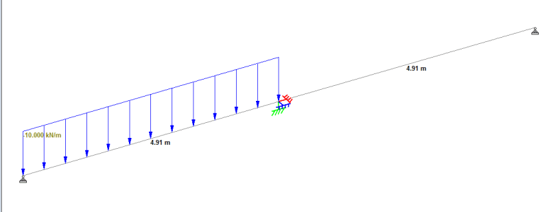
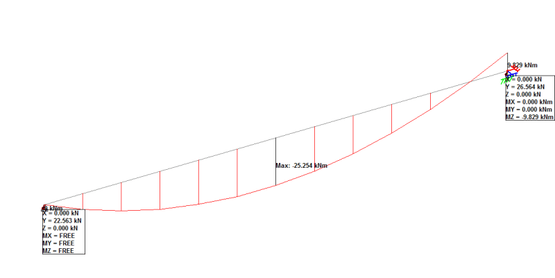
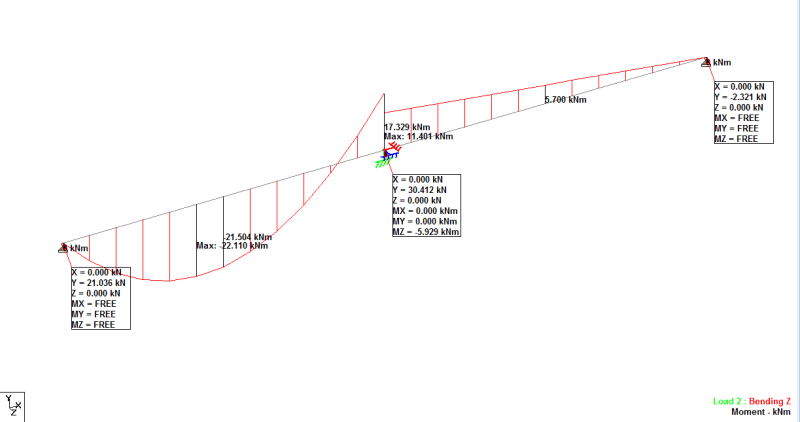
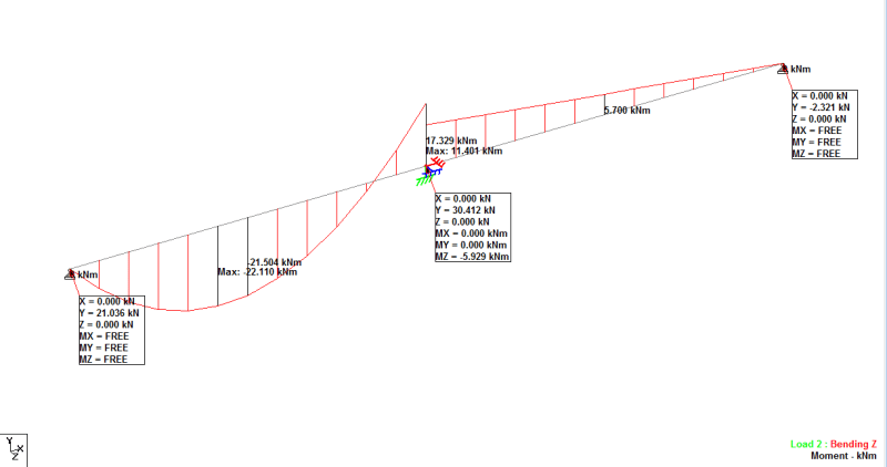
I have rebuilt a new model . It’s a 2 span beam with udl on left side only. I assigned spring support to the internal support with spring rotation = 10000kNm/degree. Here’s what I found. The reaction moment is continuous beam is somewhat lower in continuous beam compared to one span beam… I have also found that the beam moment at support for higher for continuous beam.

1.) Can I say that continuous situation making the joint stiffer, so when I applied same amount of spring at the same support in SS beam and continuous beam, the continuous beam can take higher moment? (Hogging moment at suppoort in continuous beam (17kNm) is higher than hogging moment at one span beam (9.8kNm).
2.) I also found that there’s some moment at the right end, even it’s not loaded .. Is it due to the stiffness of second beam ? The stiffness of second beam attract some value of moment to it ?
3.) Due to the attraction of moment to the second beam, this help to reduce the reaction moment at joint effectively ??

0016_rip4gm.png

0014_ylf2uq.png
0015_lqnfio.png
 
dccd said:
Can I say that continuous situation making the joint stiffer

Yes of course. The second span is another spring, which helps resist the load in the first span.

dccd said:
I also found that there’s some moment at the right end, even it’s not loaded

Again, this is what you would expect. It *IS* loaded, via the first span.

dccd said:
Due to the attraction of moment to the second beam, this help to reduce the reaction moment at joint effectively ??

Yes. The second span is another spring, which reduces the load in the first span and in the spring you added at the support.

 
Tomfh said:
Yes of course. The second span is another spring, which helps resist the load in the first span.

Do you have any idea why when I assign spring support, the moment on the right beam (right beam have no loading, UDL on left beam only) have lower value ? I am still not convinced yet.

 
dccd said:
Do you have any idea why when I assign spring support, the moment on the right beam (right beam have no loading, UDL on left beam only) have lower value ?

Because the spring has joined in (it is contributing stiffness), and the work gets shared between them.
 

I have modelled a continuous beam with continuous support , interior support is pinned, surprisingly, the moment formed at the support is higher compared to the moment when I assigned spring moment at the interior support,

how can this happen ? I thought when there's extra support , then joint will be much stiffer , hence more moment can be formed at the junction ?

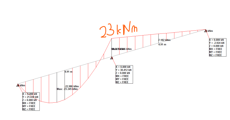
When the interior support is pinned, the moment at the junction where the beam is loaded is 17kNm, when the interios support is pinned only, the moment at the junction is somehwat higher (23kNm) , what's worng with it ?

0015_iv4rnb.png


0017_oxjwzi.png
 
Check the moment in the second case. You've written 23 kNm but all other signs point to it being 14.4 kNm.
 

Where does it show 14.4kNm ?
 
I calculated that from the other results that are visible. Eg you can simply double the 7.182 kNm at midspan since the right span moment is linear.
 

Thanks I will check out again, the 23kNm i gt it from different analysis software, the diagram was from another analysis software. I have left the model elsewhere , due to time constraint, I rebuilt the model using another sofware , and sketch the value on the diagram....

I will check the value in the old model again. I am not sure what's wrong in the new model on the different analysis software.
 
dccd said:
Where does it show 14.4kNm ?

The text isn't legible, but since the moment at mid-span of the right-hand span is 7.18 kNm, and the distribution is linear, 14.4 kNm looks like a pretty good estimate to me.


Doug Jenkins
Interactive Design Services
 
Status
Not open for further replies.

Part and Inventory Search

Sponsor