metrologic
Mechanical
Sr GDTP Y14.5-2009 Exam Review Ch-8 Part-II Sep2021
I'm in the middle of section 8, Tolerances of Profile. As you may recall, I'm working through the Y14.5 standard in preparation for upgrading my GDTP certification from the tech level to the senior level. Here is the second set of questions I had from this section:
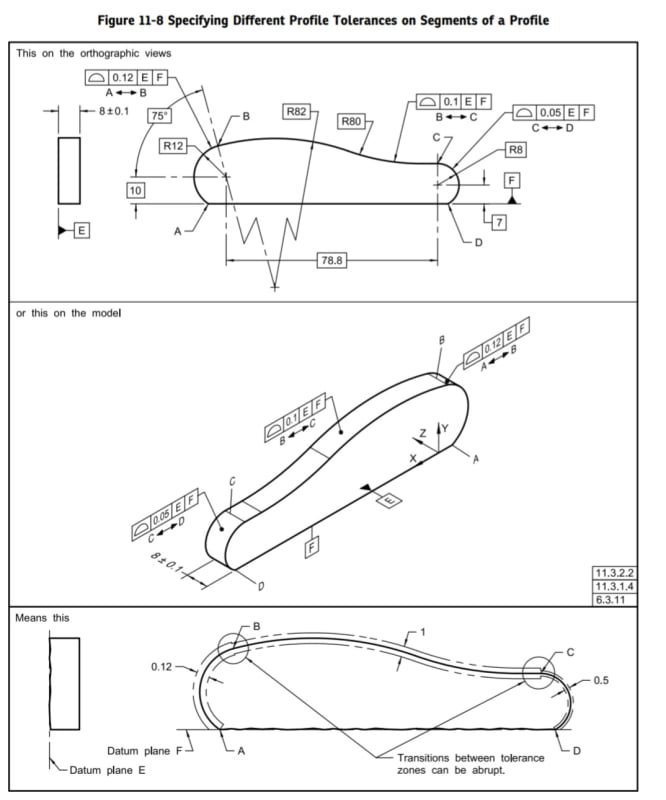
Q1. 8.3.1.5 Limited Segment of a Profile. Figure 8-6 details a part with three adjacent equal bilateral profile tolerances that control the entire continuous curvy outline except for a flat surface on its bottom. Between points A and B the tolerance is 0.12, between B and C the tolerance is 0.1, and between C and D the tolerance is 0.05. The flat bottom of the part serves as datum feature F. All the profile tolerances share the same datum reference frame |E|F|. The tolerance zones associated with the profile controls in this example are illustrated in Fig. 8-11(a). As can be seen from that figure, the tolerance zones "jump" from one zone width to another at the transition points B and C. The transitions are abrupt with tolerance zone ends that butt in to the next adjacent tolerance zone. However, where the true profile wraps around and intersects the flat bottom of datum feature F, the profile zones are trimmed off by datum plane F. Shouldn't the profile zones hang below the level of datum plane F? How does one know whether a tolerance zone should end square to the true profile or be trimmed flush with an adjacent feature?
Q2. 8.3.1.5 Limited Segment of a Profile. Back in subsection 8.3.1, Y14.5 said: "Where a profile tolerance encompasses a sharp corner, the tolerance zone extends to the intersection of the boundary lines." What happens if two profile segments with different tolerance zone widths converge at a sharp corner? Are the zone boundary lines intersected like in figure 8-12? Or do the zone boundaries feature an abrupt change from one tolerance to the next as indicated in Fig. 8-11(a) at the transition points B and C for the adjoining limited profile segments.
Q3. 8.3.1.5 Limited Segment of a Profile. "...if some segments of the profile are controlled by a profile tolerance and other segments by individually toleranced dimensions, the extent of the profile tolerance shall be indicated. See Fig. 8-7." The true profile in Fig. 8-7 is defined by some arbitrary basic dimensions and swoops from left to right between points D and E. Its extents are limited on either end by the two opposing faces of a regular feature of size. In other words, as the feature of size grows from its least material condition to its maximum material condition, the profile caught in between must naturally be enlarged in some manner. The distance between points D and E surely cannot be fixed in this example. How does one extend the true profile in these situations to fully define the tolerance requirements as the feature of size expands?
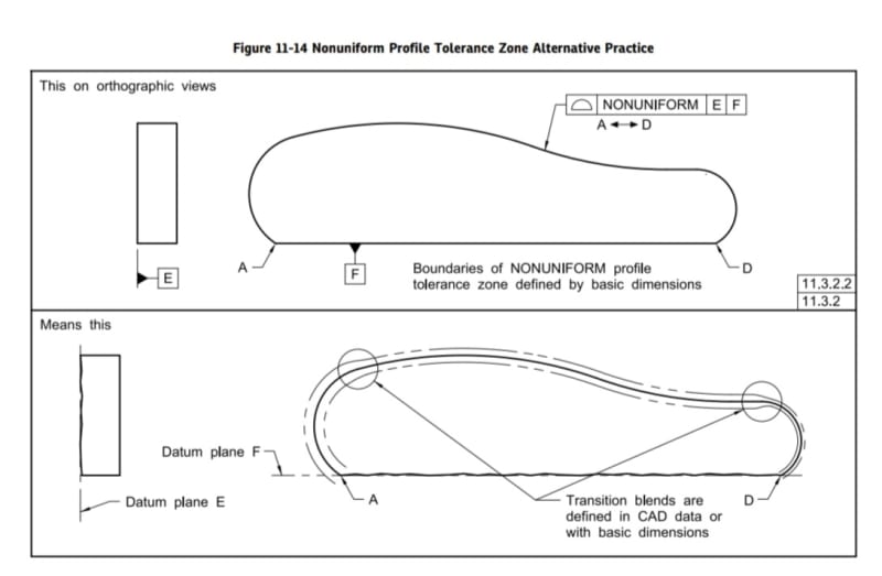
Q4. 8.3.2.2 Non-Uniform Zones to Smooth the Transitions. This subsection contains a note at the end: "NOTE: A profile per unit length, similar to that shown in Fig. 5-4 for the control of straightness, may be used to control abrupt transitions that occur when the profile tolerances are specified on adjoining segments of a feature." Profile per unit length seems like it would be a lot more complicated than a straightness or flatness per unit area. How exactly does one specify and verify a profile per unit length? What control's the orientation, location, and shape of the profile per unit length tolerance zones?


