Continue to Site

Eng-Tips is the largest engineering community on the Internet

Intelligent Work Forums for Engineering Professionals

  • Congratulations KootK on being selected by the Eng-Tips community for having the most helpful posts in the forums last week. Way to Go!

STAAD Compression Springs Issue 1

Status
Not open for further replies.

swearingen

Civil/Environmental
Feb 15, 2006
663
I'm quite sure I'm pressing the wrong button on this thing, but I can't seem to find the button...
My situation:

- Trussed industrial tower with various types and sizes of spread footings underneath.
- Lateral wind and seismic applied.
- Structure consists of steel members.
- Footings consist of concrete solids.
- Springs using a subgrade modulus of 100 pci for the stiffness (100pci x 144in^/sqft x 12in/ft / 1000lb/k = 172.8 k/ft spring stiffness per node associated with 1 square foot).
- Compression only spring specification added to the nodes at bottom.
- Lateral restraint at top of pedestals applied (grade beams between columns).

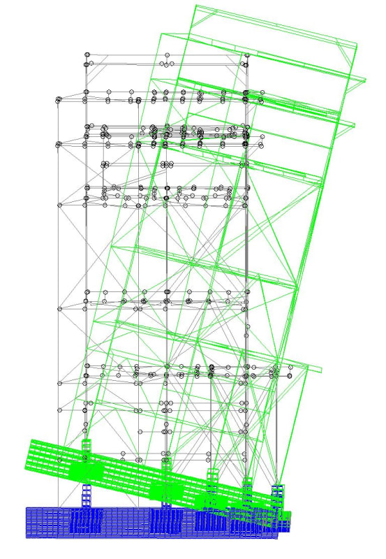
I'm getting a deflected shape that shows the entire tower rising off the ground by hundreds of inches. Things I've checked:

- Selfweight is vertical axis Y and -1.
- All loads have correct signs; gravity and equipment loads are all -Y.

It's obviously not right (as you can see from the picture). Where else can I look for errors?

Thanks in advance,

Frustrated Engineer
Tower_rakiy5.jpg


-5^2 = -25 ;-)

 
Replies continue below

Recommended for you

Have you checked consistency of input units? I've loaded models with 1000 kip when I thought I was loading 1000 lb.

Density of materials correct, especially the self weight of the foundation?

Check the sum of reactions lateral and vertical... do they make reasonable sense? Either one way off could be caused by the suggestions above.
 
@Celt83: The load case shown has self weight, equipment weight, and floor loadings, all down, included.

@PMR06: We've been going through those and haven't found anything yet. However, you can see from the deflection picture posted that ALL deflections have a positive Y component. Something goofy is going on...


-5^2 = -25 ;-)

 
Why is it obviously not right? What is your total dead load and total overturning moment?
 
The first thing I'll say is that I'm not an expert in STAAD. Far from it. I used STAAD-III back in the 90's right around the time they released STAAD-Pro. Other than that, I've always either used their competitor's software or worked direction for one of their competitors (SAP2000 and RISA).

A thought that I had from looking at your model was that some software solves a model for each load case and then uses superposition to combine the results for a combination of multiple load cases. There is a lot of computational efficiency in doing this, so it is often the default.

However, this method can be grossly inaccurate if you use it for models with non-linear elements (like compression only springs). Therefore, there may be a setting that you have to flip in order to tell the program to apply the the FULL load combinations before applying the non-linear iterations.
 
Why use compression springs? For such a model (with static loads) why not use pinned/fixed bases and check each footing individually for uplift/download?

With such results, I think you've got a localized problem where it would be faster to isolate it that way.
 
I'll caveat my comment by noting that I know nothing about STAAD other than that it uses FEA.
How have you modelled the solid element -line element connections ? In FEA, nodes of solid elements do not have any rotational fixity so if you haven't pushed your beam elements down past the face of the solids (or if you've linked them to the face without any rigid links to other solid nodes), those column and brace bases will behave as if they have moment releases at the ends. This might be what's causing your overturning issue.

I also agree with WARose's comment above - if you haven't done so already, it's definitely worth first doing a run with pinned supports at the bottom (without the footing modelled in) to see if there is any uplift at all. If there is, the next step can be to model the footing as shell elements instead of solids (this is my bias speaking as I'm more partial to shell elements).
 
You may have better luck contacting staad tech support or you can post the std file here and someone may see the modelling error. Maybe a missing CHANGE command.
 
How have you modelled the solid element -line element connections ? In FEA, nodes of solid elements do not have any rotational fixity so if you haven't pushed your beam elements down past the face of the solids (or if you've linked them to the face without any rigid links to other solid nodes), those column and brace bases will behave as if they have moment releases at the ends. This might be what's causing your overturning issue.

That's a good guess....but STAAD's solid elements do have rotational DOF at the nodes. (They didn't use to.)
 
Josh's suspicion might be on the mark. 'Load combinations' in Staad are actually result addition. The 'repeat load' commands is the way to do load combinations (obviously).
 
WARose said:
That's a good guess....but STAAD's solid elements do have rotational DOF at the nodes. (They didn't use to.)
Interesting ! Do you know if it's similar to how some FE programs provide drilling DOFs for shells?
In any case, I'd still proceed with caution and not connect linear elements to the face of solids without some extra links in there.
 
There seems to be contact between footings and superstructure along a certain width of the footing, so it seems that the case is B), not C). If this is not the case, then the other obvious answer is that the lateral loading is too big in comparison to the dead load, causing uplift.

Also, don´t forget to add vertical restraint to the superstructure-footing connection! You did not mention it in the first post. If there is no vertical restraint, the y-axis deflection may be nonzero.

PS. In all honesty, using pinned or stiff supports - not modelling the base as springs with subgrade moduli (which, by the way: is not a geotechnical parameter, is hard to estimate and can affect deflections a lot) - may be the more straightforward option. Then, only an overturning check and a sliding check (can be done by hand!) needs to be done to ensure lateral stability.
 
Interesting ! Do you know if it's similar to how some FE programs provide drilling DOFs for shells?

Not sure. I asked (some years ago) STAAD to see the shape functions for these DOF....and they wouldn't do it. It's probably a trade secret.

In tests I have done, the 8 noded "brick"/solid elements are more flexible than their plate elements: I modeled a concrete shear wall with both....and the solid elements deflected more than the plate element model. (Use to be, STADD's brick elements were ridiculously stiff.)

 
WARose said:
Not sure. I asked (some years ago) STAAD to see the shape functions for these DOF....and they wouldn't do it. It's probably a trade secret.

Maybe.... I remember reading an FEM book by MacNeal (one of the gurus behind NASTAN) where he roundly mocked plate element formulations that had a drilling degree of freedom. He said something along the lines of, "they had some leftover strain energy in their formulation that they arbitrarily threw into the drilling degree of freedom". When I was at RISA, I used to quote that line for customers when they asked if RISA could add that functionality. Years later, I remain a little skeptical of STAAD's implementation (solely because of what I perceive to be a poor development history on advanced analysis features). However, I know of other companies that I respect who also have a drilling degree of freedom for plates or a rotational degree of freedom at solid elements.

In tests I have done, the 8 noded "brick"/solid elements are more flexible than their plate elements: I modeled a concrete shear wall with both....and the solid elements deflected more than the plate element model. (Use to be, STADD's brick elements were ridiculously stiff.)
Yes, that should always be the case as modeling using bricks is adding additional degrees of freedom to the wall. If it was ever the other way, that's a good indication of a poorly formed element... at least in comparison between the solid and plate.
 
Few suggestions:
Make sure you are using REPEAT LOADs to combine load cases and not LOAD COMB. This is essential since you are using compression only springs.
Make sure you are including both gravity and lateral loads in cases that you are interested in.
Connectivity between beam elements and solids could be tricky as solids do not have rotational DOFs. I would use beam elements for pedestals and plate mesh for the footings.
 
Connectivity between beam elements and solids could be tricky as solids do not have rotational DOFs.

Sye, are you sure of that? (IIRC, you work/have worked for STAAD so you'd be the guy to ask.) I'm almost 100% sure that they told me some years back [about 10 IIRC] that they added rotational DOF to solids. If they haven't, why is it you don't get error messages anymore when you fix a node [i.e. designate a fixed support] on a solid? Use to be, you did get such a error. Also, if they haven't introduced those DOF....why are solids so much more flexible in STAAD than they use to be? Thanks.
 
WARose:

I assume that Sye123 was referring to structural mechanics and the conventional FEM formulation, in which 3D deformation is represented by displacement components (w, v, u), and no rotation. This is the formulation that I have seen in university and in textbooks, and it is the only formulation that makes sense, if you think about it a bit further.

For there to exist a rotational DOF, you must define around which axis (for beams: around one axis along a line; for plates: around two axes in a plane) the rotation occurs. Let´s say that you have a 3D solid, such as a tetrahedron, and add some nodes (say- at the corners) and element interpolants. Now, the choice of "rotation around an axis" becomes completely arbitrary for any node in the solid: what is the reference plane that a corner node "rotates around"? The answer is that there is no uniquely identifiable axes for each component (w, v, u) to rotate around (there are infinitely many choices of such axes!), because no dimension reduction assumptions are made in the 3D solid modelling. Rotational degrees of freedom are borne out of dimension reduction (bar, beam, plate, shell) models.

Mathematics can be used to derive complicated models that are not necessarily physical, and the "solid element with rotational degrees of freedom" is one of those unphysical models.
 
Status
Not open for further replies.

Part and Inventory Search

Sponsor