I’ve seen a lot of discussion about scissor/vaulted trusses here and there seems to be a consensus in the overall design approach.
1. Try to restrict the truss from moving (due to truss deflection) and impart a large thrust load on the supporting structure.
2. Allow the truss to displace as a pin-roller connection and check to make sure your walls can handle the displacement.
It looks like most of you have agreed that making a structure stiff enough to withstand the required truss deflection would be a futile exercise. Also it’s not so much the type of truss connection that allows this displacement (ie using one of those Simpson “slip connections”) but rather the lack of infinite stiffness from a wall support that give you the theoretical roller (makes more sense to me with wood than the scenario I'm about to present).
In both situations, the stiffer the truss members and the less overall deflection the truss experiences, the less the horizontal reaction if the truss was pin-pin, and the less the horizontal deflection for a pin-roller.
Good so far? Is there anything I’ve misinterpreted?
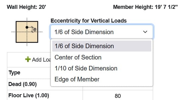
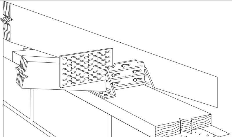
Most of my projects don't utilize wood construction for the wall system. 99% of the time I have bond beam/tie beam with CMU or concrete construction. Sometimes I even have concrete portal frames as discussed below. The way I treat most of my regular truss type conditions/non-scissor type (that is, in order to stay in line with the truss designer utilizing a pin-roller approach) is to consider that most of Simpson's truss connectors will deflect in the F1 direction, no matter what the given F1 load is. Here is some language from the Simpson Catalog:
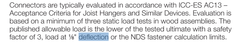

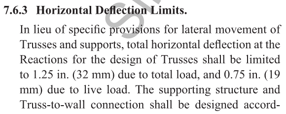
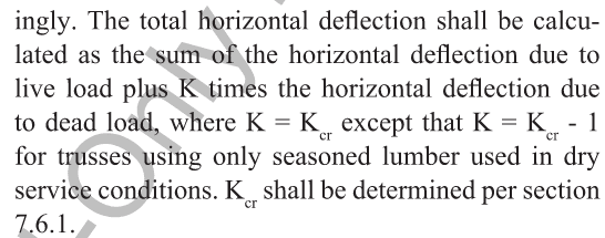
So given the fact that a typical connector has up to an 1/8" deflection and the Truss Design Documents for typical trusses have a horizontal creep total (CT) that doesn't exceed these values, you can assume the designated end of the truss is able to displace. [highlight #FCE94F]You usually don't find engineers who are arguing that their tie-beams are laterally displacing enough to provide a roller support.[/highlight]. I realize this invalidates what some of you had said about a truss not being able to displace due to friction at the connection, or the diaphragm working in unison. To be honest, I don't know how to qualify the fact that all our truss designers use pin-roller if not for this.
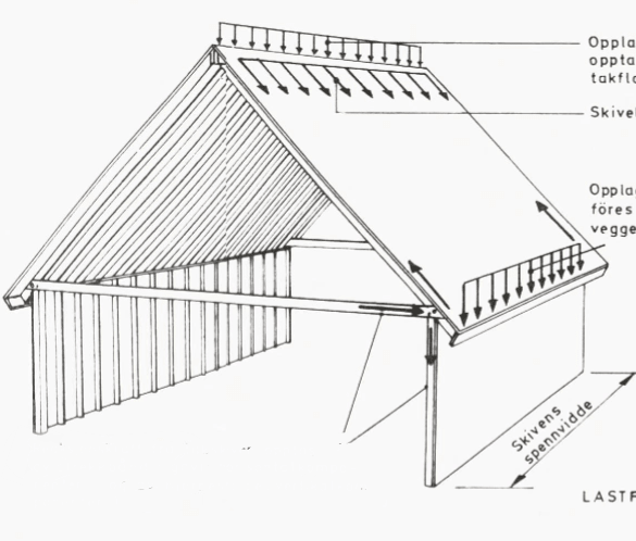
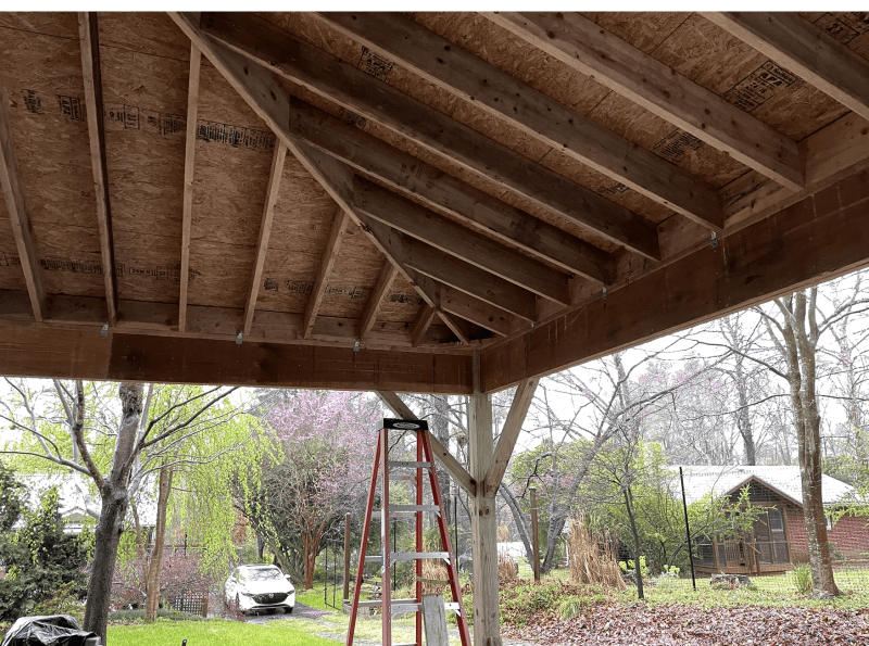
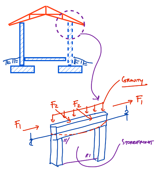
So how do we handle the stability analysis in a situation like this? To better explain my situation, I’m looking to do a cathedral style roof that sits on a concrete portal frame with storefront infill below the frame. So I will have lateral loading in the plane of the portal frame (F1), gravity load from the roof truss, and an assumed F2 due to wind load on the walls (windward, leeward, side wall) in addition to a F2 from the thrust load of the truss (btw its' so interesting how all this is going on but rarely gets illustrated). With a cathedral ceiling, I don't see how I can take the same liberties that I do for typical a common truss. So how should I handle the stability analysis?
Also:
When doing cathedral style roofs:
1. Is is common for the architect or GC to put the truss designer and structural EOR in connection prior to the development of construction documents. So often I'm supposed to wait a month out until the truss design can get me the TDD reactions, and for a truss like this it's putting the cart in front of the horse.
2. Is there a better way to handle the trust reactions? I must have no tension rods, no ceiling at the tie-beam elevation, a maximum sloped vault inside the structure, no ridge beam or columns to break up the spans, and there cannot be buttresses or pier cast into the wall (ie, inside face of walls all have to be uniform).
1. Try to restrict the truss from moving (due to truss deflection) and impart a large thrust load on the supporting structure.
2. Allow the truss to displace as a pin-roller connection and check to make sure your walls can handle the displacement.
It looks like most of you have agreed that making a structure stiff enough to withstand the required truss deflection would be a futile exercise. Also it’s not so much the type of truss connection that allows this displacement (ie using one of those Simpson “slip connections”) but rather the lack of infinite stiffness from a wall support that give you the theoretical roller (makes more sense to me with wood than the scenario I'm about to present).
In both situations, the stiffer the truss members and the less overall deflection the truss experiences, the less the horizontal reaction if the truss was pin-pin, and the less the horizontal deflection for a pin-roller.
Good so far? Is there anything I’ve misinterpreted?
Most of my projects don't utilize wood construction for the wall system. 99% of the time I have bond beam/tie beam with CMU or concrete construction. Sometimes I even have concrete portal frames as discussed below. The way I treat most of my regular truss type conditions/non-scissor type (that is, in order to stay in line with the truss designer utilizing a pin-roller approach) is to consider that most of Simpson's truss connectors will deflect in the F1 direction, no matter what the given F1 load is. Here is some language from the Simpson Catalog:
So given the fact that a typical connector has up to an 1/8" deflection and the Truss Design Documents for typical trusses have a horizontal creep total (CT) that doesn't exceed these values, you can assume the designated end of the truss is able to displace. [highlight #FCE94F]You usually don't find engineers who are arguing that their tie-beams are laterally displacing enough to provide a roller support.[/highlight]. I realize this invalidates what some of you had said about a truss not being able to displace due to friction at the connection, or the diaphragm working in unison. To be honest, I don't know how to qualify the fact that all our truss designers use pin-roller if not for this.
So how do we handle the stability analysis in a situation like this? To better explain my situation, I’m looking to do a cathedral style roof that sits on a concrete portal frame with storefront infill below the frame. So I will have lateral loading in the plane of the portal frame (F1), gravity load from the roof truss, and an assumed F2 due to wind load on the walls (windward, leeward, side wall) in addition to a F2 from the thrust load of the truss (btw its' so interesting how all this is going on but rarely gets illustrated). With a cathedral ceiling, I don't see how I can take the same liberties that I do for typical a common truss. So how should I handle the stability analysis?
Also:
When doing cathedral style roofs:
1. Is is common for the architect or GC to put the truss designer and structural EOR in connection prior to the development of construction documents. So often I'm supposed to wait a month out until the truss design can get me the TDD reactions, and for a truss like this it's putting the cart in front of the horse.
2. Is there a better way to handle the trust reactions? I must have no tension rods, no ceiling at the tie-beam elevation, a maximum sloped vault inside the structure, no ridge beam or columns to break up the spans, and there cannot be buttresses or pier cast into the wall (ie, inside face of walls all have to be uniform).
")