Continue to Site

Eng-Tips is the largest engineering community on the Internet

Intelligent Work Forums for Engineering Professionals

  • Congratulations GregLocock on being selected by the Eng-Tips community for having the most helpful posts in the forums last week. Way to Go!

Stability of soldier pile retaining wall 1

Status
Not open for further replies.

t230917

Structural
Apr 24, 2019
51
I am designing a soldier pile wall for the first time with the following:

Retained height - 11.2'
Ka=0.46, Kp=1.6 (after using reduction factor from AASHTO), pile spacing=8', concrete dia.=3', phi=30 degrees, unit weight-120 pcf from backfill to excavated height, and then reduces to 80 pcf, LL surcharge=250 psf on both faces.
Based on this, I am getting a depth of embedment of 21'.

I had 2 questions in regards to this. 1) Does the depth of embedment look right?
2) How do I calculate the stability of this wall? I cant find the procedure for this.

Thank you.
 
Replies continue below

Recommended for you

Thank you for letting me know about the overturning and sliding checks. How do I check for the rotational stability?

I am trying to stay away from hard rock, hence the use of 3' diameter shafts. If I go down to 2.5' which is the minimum that I need, the contractor would have to drill into rock. Right now, the bottom of pile embedment is at least 1' above the top of rock elevation.

Would construction of cast in place concrete lagging work? Also, to clarify, there is 3" of untreated timber lagging, and the facing is 12" concrete facing.
 
Sorry my previous post was before reading the latest 3 posts.

So in essence, when I designed the depth of embedment by summing the moments about the pile tip as zero, this was simultaneously being checked for overturning, is that correct?

I understand the point about not checking for sliding because of the passive pressure. Do I still need to check for rotational stability?
 
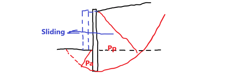
Provides the pile embedment is greater than, or equal to, the design called for, do you think the failures in the sketch can occur?

s_dpjd4g.png
 
The way I think about it, rotational stability is the only stability check/design that is applicable to a soldier pile wall. Structural capacity for the max moment and shear, of course, must also be adequate. In some instances, excessive deflection may also be a design criterion. To calculate deflection, if it matters, I suggest using P-y curve analysis software, such as Allpile or Lpile.

There is no sliding for a non-gravity wall. There may be some lateral deflection at the dredge line (always much less than at the top) to engage the passive resistance of the embedment soil in front of the wall, but it cannot fail in sliding, so attempting to apply any spec. provisions concerning sliding to this type of wall will only lead to confusion and/or incorrect conclusions.

Rod Smith, P.E., The artist formerly known as HotRod10
 
I still think overturning check is not required for the soldier wall. The reason is the design is liking play lever scale with known weight "A" at one end, and slide the other weight "B" to "maintain the balance". Once the balance point is found, then we further slide "B" a little down the scale to ensure it will not under weigh the far end weight "A", that is - no overturn is possible. Similarly, the overturning phenomenon is implicitly rendered non-issue in the design by finding the embedment length required for balance, and extend it for extra safety. Thus there is nothing to check, stability wise, after the design.

In contrast to the one dimensional pile design, the cantilever retaining wall design is two dimensional, and is less straight forward. The length of the base slab is pre-determined through bearing and successful trail iterations on overturning, the balanced condition is difficult to reach/observe, and can only be confirmed through the check of "over turning" and "sliding" with satisfactory safety factors for all given conditions. Thus, post design stability check (overturning and sliding) is essential for the cantilever retaining wall.

Hope the comparison above makes sense.
 
Hope the comparison above makes sense.

It does. I think you summarized the soldier pile wall stability design well. Your cantilever retaining wall summary is missing the 3rd typical stability check - foundation bearing capacity.

Of course, there's structural design for shear and moment for both - simple cantilever bending for the soldier pile, and bending on the heel, stem and toe for a cantilever retaining wall.

Rod Smith, P.E., The artist formerly known as HotRod10
 
Rod,

Thanks for the comment. I think the posting you read was my original work. Here is the updated version:
...the cantilever retaining wall design is two dimensional, and is less straight forward. The length of the base slab is pre-determined through bearing and successful trail iterations on overturning, ...
 
The statement about bearing may have been there, and I just missed it, retired13. I usually try a few different combinations of base slab length and stem wall location to optimize the configuration.

Rod Smith, P.E., The artist formerly known as HotRod10
 
Status
Not open for further replies.

Part and Inventory Search

Sponsor