Eng-Tips is the largest engineering community on the Internet

Intelligent Work Forums for Engineering Professionals

  • Congratulations waross on being selected by the Tek-Tips community for having the most helpful posts in the forums last week. Way to Go!

Stacked pipes. Load to upright supports. 1

Status
Not open for further replies.

MarioGr

Structural
May 28, 2014
28
0
0
AU
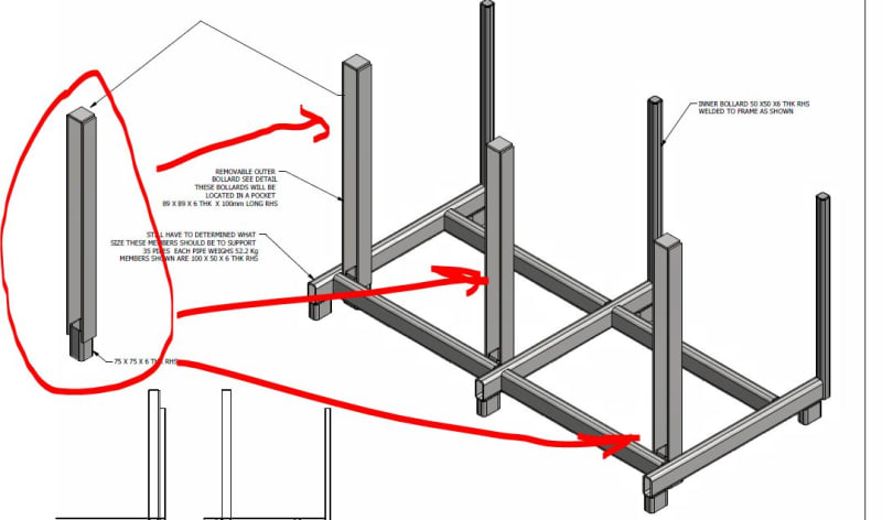
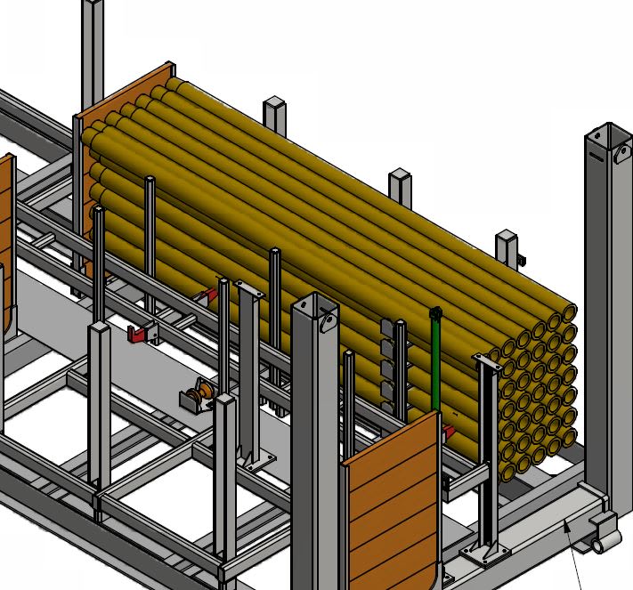
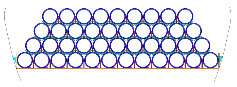
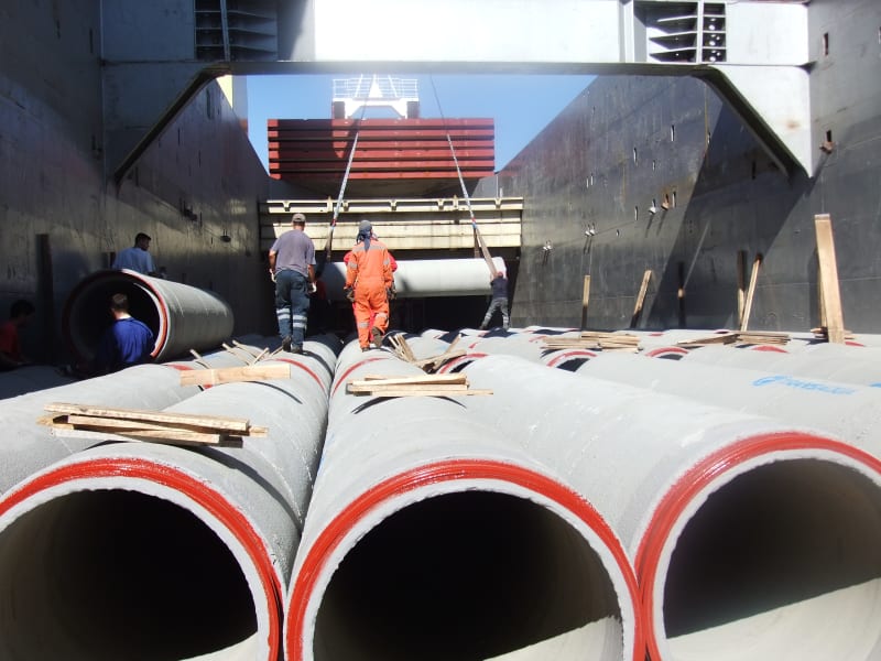
I have a situation where some pipes need to be stacked 7 rows high by 6 pipes across. Each pipe weighs approx 50kg.

They're stacked on top of each other. Now if this container held soil or water the loads to the uprights would be easy to calculate but in this case I'm unsure how to proceed.

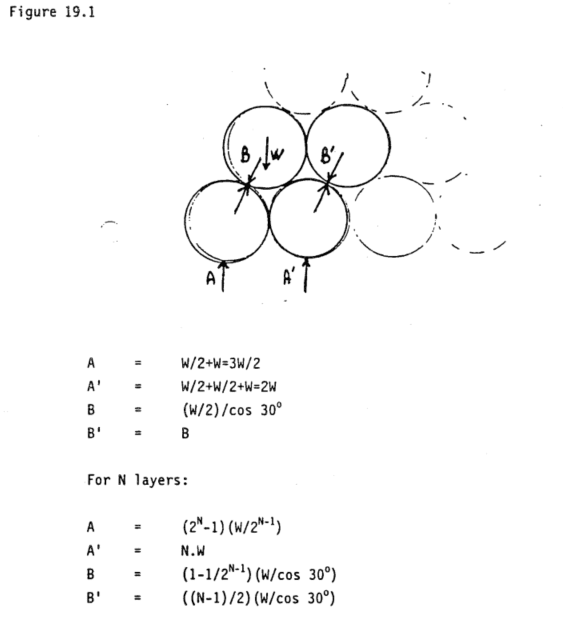
Obviously if the supports were t0 be removed the pipe stack would collapse. It follows that there is a horizontal component of the load at some point on the uprights. Again if this were soil or water there would be a triangular distribution and the centroid of the load would be 1/3 up from the base. From there it would be easy to calculate the moment.

Can anyone here help? Thanks in advance.

Capture_vyaqxx.jpg
 
Replies continue below

Recommended for you


In theory if the pipes are stacked as you show, I.e. Centre of pipes vertical then there is no horizontal force.

Reality is that there is some non uniformity in the stack but horizontal force is 5% or less of the vertical force.

Any movement of the stack will create forces caused by momentum change and acceleration. That's one up to you to work out.

Remember - More details = better answers
Also: If you get a response it's polite to respond to it.
 
If the gap between the uprights was precisely equal to the width of 6 pipes, there would be no horizontal force (in theory).

Obviously there must be some small gaps that allow the pipes to be stacked without being too snug.

I would consider the situation where each consecutive row of 6 pipes is squished up against an alternating side, then work out the horizontal components of force that results. This obviously depends a lot on the width of the gap, which may increase even more with the outward force from the pipes.
 
The draftsman showed them exactly one over the other one. In reality it'd be (b) as shown above.

In which case what is the horizontal component of the dead weight.

I've cadded the pipes up in a DWG and if they're touching as shown on (b) then a line drawn from centre of pipe above to centre of pipe below is exactly 30 degrees from vertical.

Given that I'm wondering whether a just resolve the vertical force into one at 30 degrees to the vertical and then find the horizontal component?
 
there's a difference between the multi stacked pipes in the open and option B

For option B you need to look at the single stack which is a triangle 6 pipes wide by 6 pipes tall within the bundle to get horizontal load at the base acting half a pipe diameter up from the base.

Then each pipe on the outside layer contributes half its weight to the next one and so on then you have sin 30 x total weight /2 x 5 layers. Note that weight is also divided by the number of supports.

Then the next outer layer is the same as its six pipes in a row at 30 degrees,

Then the next pipe to contact the side is only 3 pipes acting on the outer pipe

Then only on pipe at the top.

All this ignores friction which is why some pipe stacks can exhibit very low horizontal forces and others collapse.

Also do the pipes really stack together edge to edge with uniform contact? introduce any sort of spacer, be it wood or rope and you're in a different place altogether.

Option B is marginally more efficient (44 pipes vs 42 pipes as drawn.)


Remember - More details = better answers
Also: If you get a response it's polite to respond to it.
 
MarioGr said:
...if this were... water there would be a triangular distribution and the centroid of the load would be 1/3 up from the base.

I would do exactly that to calculate of the upper bound of horizontal force... consider the pipes to be a "fluid" with weight (42 each x 50 kg / each), length, height, and width known. Do to math to determine the "density" of the "fluid" and proceed as you have mentioned.

Even the conservative calculated horizontal force is likely not high enough for a real industrial application. I would apply a safety factor, say, a value of two, to account for unintended forces applied as the the pipes are loaded or unloaded.

[idea]
 
This is from a famous pipe stacking calculation for pipes on the ground.

50% of vertical is way over the top.

image_hphrbj.png


Remember - More details = better answers
Also: If you get a response it's polite to respond to it.
 
Of course. But its only a few meters of columns. If you want theory, all the load is down.
And if one on those pipes is on the outside, rather than inside, your weight is directed out, not down. And you can't stack them perfectly vertical, without posts, so you know that they would roll outward somewhere and they fall like a house of cards. Its not a stable structure. A little sun on the outside pipes might be enough to get some thermal bending and ... down they go. Even to stack them triangularly, you still need some blocks or sand berms to keep the bottom pipes in position, otherwise they will roll out.

I think you have to assume that it will act more like a retaining wall with some lateral load, whether its 50% of pipe weight, or something less, fine. Maybe just 50% of the immediately adjacent pipes is enough for providing stability.

My point was that for such a small amount of steel in 4 or 6 something columns, making a huge calculation out of it doesn't seem like very necessary. W8x31 and hit the road.

 
Thanks to all. Unfortunately I cannot just specify a giant member and be done with it They have constraints on what we can but irrespective of that I was interested out of professional curiosity as to how this stacked pipes would distribute there load.

I've used a combination of methods plus my own to get various values and conservatively used that to check the uprights.

Cheers again.

 
Yes. I guess that's why you asked.
W8X31 isn't exactly "giant". Its actually quite small.
But yes, perhaps too much for this situation.
In reality you probably don't need more than a 4x4 wooden post, but your nice drawing made me think you wanted something that might withstand some movement.
What is it?
 
^^ 3 of 50 x 6.0 SHS post one side. 3 of 75 x 10 flat bar x 2 (side by side with a gap for a lifter) on the other side.

I'm in Australia and I wasn't sure what a W8 x 31 was.
 
This forum UI is old skool. Can you quote posts?

With regards the above they're only 1100mm high. And there's 3 of them. (It checks out.)

Here's a picture which may help.

Capture_qd0xga.jpg
 
I realise this is hardly end of the world stuff. I was wondering out of professional curiosity how it's done and/or if there's a formula.

Who knows. One day I might have to design some bollards to contain pipes 100ft high.
 
Status
Not open for further replies.
Back
Top