Continue to Site

Eng-Tips is the largest engineering community on the Internet

Intelligent Work Forums for Engineering Professionals

  • Congratulations SSS148 on being selected by the Eng-Tips community for having the most helpful posts in the forums last week. Way to Go!

Stainless Steel Square 1/2" U Bolt Failure 6

Status
Not open for further replies.

mtgski

Automotive
Jun 12, 2020
6
Looking for some insight on a failure of a Stainless Steel Square 1/2" U bolt. 3 1/2" legs and 5 3?4" wide inside. Rated for 5000 pounds capacity with a 20% over factor so 7000 pounds.

Background: this is one of 4 U bolts used on the lifting bunks of a boat hoist that hold up the boat on the lifting frame. Overall capacity of the lift is 4000 pounds ( these U bolts are normally used on a 5000 pound capacity rated boat lift) Boat wet weight is 3500 pounds. The U bolts in questions were brand new last year, used for 5 months on a boat lift in fresh water. The U boats and bunks were removed from one lift to install on another lift this year. On the second day of the boat being loaded on the lift the failure occurred on one of the four U bolts about 45 minutes after the boat was put on the lift.

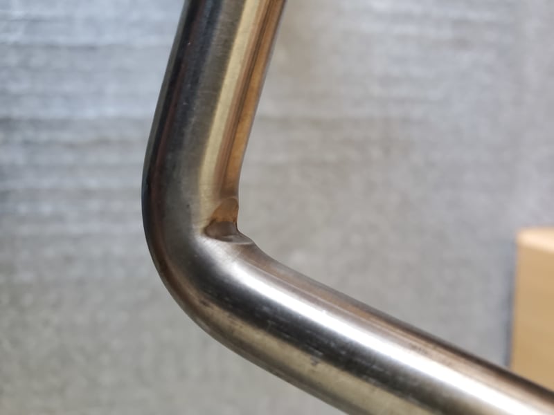
Do you think the tooling mark creases or cuts into the inside corners of the U bolt contributed to the failure? ( since the failure point was at or very near these tooling marks)

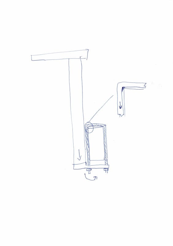
Would the angle of the single U bolt when mounted, with the upper and lower portions not being vertically aligned with each other, have any affect on the load contributing to the failure?

Brand new U bolt
20200612_123833_1_an4hnh.jpg


One of the three remaining one year old U bolts
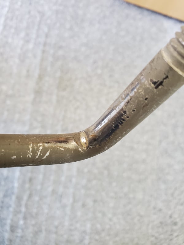
20200611_112134_1_pashkh.jpg


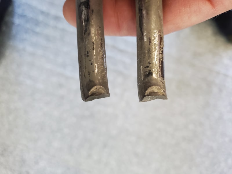
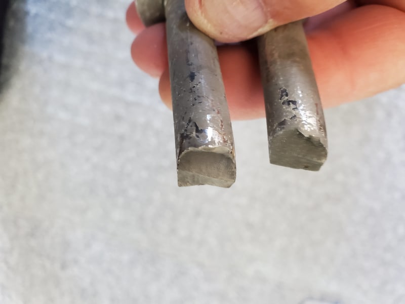
Failed U bolt, inside of bend area
20200611_112321_1_i54gua.jpg


Failed U bolt, outside of bend area
20200611_112338_1_pqpcyl.jpg


Angle of the lifting bunks, U bolts were offset at an angle about 3 1/2" off center due to 5" cross-member tube and 5 7/8" inside U bolt width.
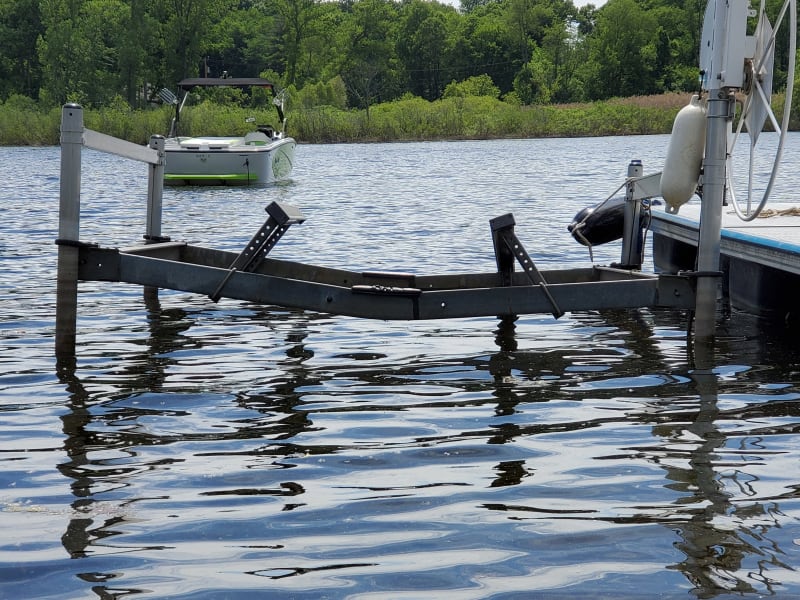
20200609_151940_1_v2wjkd.jpg
 
Replies continue below

Recommended for you

What alloy, 304?
I'll wager that if you use a strong magnet you find the area near the fracture fairly ferromagnetic.
The notch from the forming and the lower ductility from the cold work is not a good combination.
Moving them likely changed the stresses in them (twisted differently or not quite tight enough) and lead to failure.
Hard to tell from your photo but it does not look any deformation adjacent to the fracture.
This really points to Environmentally Assisted Cracking of some sort to me.
Where in the country is this?

= = = = = = = = = = = = = = = = = = = =
P.E. Metallurgy, consulting work welcomed
 
Just a couple of observations ....

1) Was your failed U-Bolt Hardware made in China ?

2) Is the bolt configuration available in larger diameters than 1/2" ?

3) Is there any way you could come up with a weight and test your own purchased hardware ?

4) I do not believe that the age of the hardware or the environmental conditions have anything to do with the failure

Unfortunately, square u-bolts are a bit of a mongrel configuration in the rigging hardware world. There seems to be no standard way to load, configure and test these things. The manufacturer's sales information on maximum loads seems to be just estimates, IMHO ....

ASME has dimensional standards for "round bend" u-bolts, but not square .... as far as I can tell


The Portland bolt people offer some guidelines on the minimum required bend diameter of a properly made square u-bolt. You failed U-bolt does not seem to meet these minimum requirements.


MJCronin
Sr. Process Engineer
 
Note, in the US the lifting device shall have a safety factor from 2-4. If the bolt failed at weight below the rated capacity, it could indicate there was problem during manufacturing.
 
Thank you for all your comments and assessments. Besides the $ 1,000.00 plus damage to my one year old boat, I am more concerned with preventing this type of failure for anyone else that may purchase these replacement U bolts from a boat lift parts store like I did. My boat damage can be repaired but had that U bolt failed while lifting the boat up and had someone been to close to or standing on or leaning on the lift during that time it could have been a life changing injury or death!!

I do not know the actual number of the Stainless alloy, trying to find out. Is there a easy way to find that out?

Yes, they were made in China, as confirmed by the US lift manufacturer prior to clamming up and giving me a standard lawyer statement saying they are not liable for use of their component products on any other brands of boat lifts beside their boat lifts. Which is the main problem as I was sold these replacement U bolts by one of their local boat lift distributors to use specifically on a different brand of boat lift.

Yes, there is ferromagnetism when a strong magnet is applied to the fractured area. The outer portion of the failed U Bolt does show some Ferromagnetism but to a much lessor degree than on the inside. On the brand new U bolt pictured the same magnet will not stick to any of the main body of the U bolt but will stick in the crease on the inside of the bend and to the outside of the bend and on the threaded areas.

I do not see any deformations adjacent to the fracture. There are some radial striations in the outer portion of the bends that look like stretching of the metal. I suppose this is normal as that is what is happening to get the bend to form.

This is in southern Michigan in a fresh water in-land lake. Hoist is removed from the water in the winter to avoid damage by ice.
 
You would be better off having a cross bar made with two holes in it, and then using straight bolts.
The cross bar could even have 'shoulders' on it so that it would fit well up against the main structure.
I wouldn't use bolts made this way, it is asking for issues.
There is no easy way to test for the alloy, unless you know someone that has access to one of the hand held XRF analysis guns at work.

= = = = = = = = = = = = = = = = = = = =
P.E. Metallurgy, consulting work welcomed
 
hmmm this should be turned in to the governing board to address this safety issue.

shop a round with a more reputable dealer with certifications for the product.
 
Report to consumer protection agency of the state where the purchase was made. Thought you might not be able to get your money back, the agency might investigate, and sanction against the product.
 
Haven't any of you commenters taken a course in strength of materials where stress concentration is discussed? Obviously that sharp interior corner has high stress concentration there. It is not uniformly distributed. You could duplicate this by taking two "U" bolts, one with a smooth corner and the other with that corner containing a notch. Find the cross sectional area of each and compute stress. This is simple text book stuff. Even the unnotched corner looks too sharp.

Do a simple Internet check using "notch radius" and a whole lot of info is out there.

More edit: I'd go to the person that created the system for lifting. The bending of the member and the darned dumb notch is crazy construction. Look at a structural member horizontal under the boat and eye bolts of similar to transfer the load at that lower corner of the bracket to he vertical position. No bending stuff please. With care by welding that corner it may work also.
 
OG, In this case it is even worse. They have a bad geometry, and they have bad material properties from the excessive forming.
Definitely needs to be done differently.

= = = = = = = = = = = = = = = = = = = =
P.E. Metallurgy, consulting work welcomed
 
It looks like the angled installation puts a twist load on the ubolt. There would be combined twisting and bending at the bend. The nuts may not have been tightened enough to create enough friction force to carry any the loads. I don't think ubolts carry side loads very well. Their ratings are tensile loads.

Ted
 
@hydtools Yes probably needs eyebolts instead or a bracket bolted to hold the
The weight. No side load.
 
Hi mtgski

All the things that you mention could have contributed to the failure but the one thing that hasn’t been mentioned yet is the ‘u’bolts have been removed and then reused this could be quite a big no no, reusing fasteners of any type can be disastrous particularly if there is no records of what they were preloaded too. So my question how and what preload were those ‘u’ bolts loaded too.

“Do not worry about your problems with mathematics, I assure you mine are far greater.” Albert Einstein
 
mtgski

"Do you think the tooling mark creases or cuts into the inside corners of the U bolt contributed to the failure? ( since the failure point was at or very near these tooling marks)."

Yes - It looks to me like someone is trying to get these square bolts to fit exactly over a square beam / channel / box section. So if the inside edge to inside edge of the U bolt was say 4 inches, then it was designed to fit over a 4 inch wide beam/flange with absolutely minimal clearance. Otherwise any gap between the edge of the beam and the corner you will get a significant bending moment on the inside edge and truly horrendous stress concentrations there. Also as you can see from the failed sections the diameter of the bar is reduced where this notch has appeared.

"Would the angle of the single U bolt when mounted, with the upper and lower portions not being vertically aligned with each other, have any affect on the load contributing to the failure?"

Also yes but that single picture is unclear as to how the boat "lifting bunks?" are actually attached to the frame and how , if at all, these are tightened. Needs more pictures or a drawing / side on view. Are these bunks designed to slide to fit the particualr boat? Is there any tension on the bolt before the boat is lifted out of the water? The existing bolts seem to have scrape marks on them?

I diodn't quite understand this bit "Angle of the lifting bunks, U bolts were offset at an angle about 3 1/2" off center due to 5" cross-member tube and 5 7/8" inside U bolt width. I didn't quite understand this bit " Can you explain / draw what you mean?"

Where is the load path?

Does the bolt go through the holes visible in the lifting bunk to adjust height?

Even if not the load would appear to be concentrated on one side only so I'm far from surprised this broke. The moment from only one side being loaded will create bending forces in the bolt and result in virtually all the weight of the boat being taken in one corner of the bolt. Poor design IMHO. Better to have something in shear than tension like this. Did it look something like this in section?

[EDIT] - NOw incorrect picture - close but see more info from the OP further down the post]

CCI_000001_1_lg91pn.jpg


Remember - More details = better answers
Also: If you get a response it's polite to respond to it.
 
OK, i think I understand things better now ....

My suggestions:

1) Buy slightly larger diameter quality SS bolts (5/8") without the corner notch and replace the old bolts OR

2) Use TWO 1/2" bolts side-by-side to support your beam and redesign the hardware OR

3) Redesign the support structure where the moment is taken out of the square u-bolt by either a brace or use of two robust flat plates (sandwich) and interconnecting bolts.

My opinions only ...


MJCronin
Sr. Process Engineer
 
In my opinion, the v notch is there to relief stress concentration by design. But I don't know how effective it is. Isn't there any process method can make smooth u-bolt?
 
retired13 said:
the v notch is there to relief stress concentration by design

Care to explain this one a bit more?

Any bending moment on that 90 degree angle end will result in high stress concentrations at the root of the V notch. Not to mention reduced diameter of the rod or decrease in torsional strength.

I would say it's not in the slightest bit effective.

Remember - More details = better answers
Also: If you get a response it's polite to respond to it.
 
Tilmore Farm Products uses these bolts in their cross tube clamps. The bolts appear identical with the notch and all. Am I morally required to advise them of our findings?
 
In an application that has no twist or bend to it these are just a little bad, but anything other than a straight pull and these are not to be considered usable.
And never use them anywhere it would be possible to have any exposure to salt.

= = = = = = = = = = = = = = = = = = = =
P.E. Metallurgy, consulting work welcomed
 
Status
Not open for further replies.

Part and Inventory Search

Sponsor