Continue to Site

Eng-Tips is the largest engineering community on the Internet

Intelligent Work Forums for Engineering Professionals

  • Congratulations MintJulep on being selected by the Eng-Tips community for having the most helpful posts in the forums last week. Way to Go!

Statically Indeterminant Beam Problem 7

LFRIII

Mechanical
Sep 2, 2022
19
I am trying to solve the following problem which is in the method of superposition section of my Strength of Materials textbook. I am stuck and am wondering if anyone could point me in the right direction.

A beam of length 3L is supported by four supports, A, B, C, and D from left to right. The distance between any two supports is L. Between the two middle supports, B and C is a uniformly varying load with maximum intensity of w. Find reactions Ra and Rd.

I started by eliminating the two redundant reactions at A and D and used Case 10 Simple Beam with Uniformly Varying Load (see attached) to find the slope at points B and C. Then used Case 9 Simply Supported Beam with Couple Moment at End to find the moments a points B and C. From there I have tried many things without success.

The book gives the answer: Ra = wl/45; Rb = wl/36.

If anyone can help with this, I would appreciate it.

[URL unfurl="true"]https://res.cloudinary.com/engineering-com/image/upload/v1726255246/tips/Beam_Deflection_Formulae_iqr6vc.pdf[/url]
 
Replies continue below

Recommended for you

RB1957 said:
different loading, no?
No!

The method of superposition combines the effects W, Ra and Rd. Each is considered separately.

Load W bends the middle beam down and slopes the end spans up.
Ra and Rd bend the end beams down to bring delta A and delta D to zero.
Load P represents both Ra and Rd, but Rd is flipped horizontally.

Equ. 1 Delta A = Delta A[W]+Delta A[Ra]+Delta A[Rd] (square brackets means due to)
Equ. 2 Delta D = Delta D[W]+Delta D[Ra]+Delta D[Rd]

Finally, solve Equ. 1 and 2 for Ra and Rd.
 
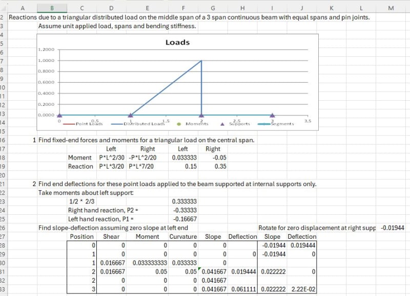
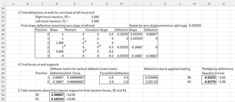
Here are my calculations with the end supports removed to get a determinate structure, then apply a unit load to the left hand end to find the end reactions required to bring the deflections back to zero:

Engtips19Sep24-1_ygnpmt.jpg
Engtips19Sep24-2_bwhrn0.jpg


Results are (of course!) exactly the same as before.


Doug Jenkins
Interactive Design Services
 
Celt83 the method that you have used in determining slopes and deflections for the unknown reactions is called the Myosotis method by Den Hartog.
 
Gentlemen:

I thought I had this. I understand how to solve my original problem with the VDL using superposition setting angles equal to each other. After working it out it seemed simple. But I am now trying to apply this to a real world problem where I know what the answers are but am unable to get my calculations to work.

Here is the problem.
Beam Configuration: 4 supports A,B,C,D
Distance between end supports and middle supports: a = 6"
Distance between middle supports B and C: L = 62"
Load: Wo * sin(PI*x/L)S
Beam Moment of Inertial: .785 In^4
Elasticity: 29 x 10^6 Lb/In^2
Wo: 82.815 Lb/In
Slope at the ends of a simply supported beam with sine load Slope θ = WoL^3/π^3EI.

Solution: Ra & Rd = -3,214 Lb, Rb & Rc = 4,848 Lb

Due to Wo:
Slope at Support B = WoL^3/π^3EI.
Slope a Cantilever Beam θ = Pl^2/2EI @ l = a ==> Pa^2/2EI
slope at Support A = WoL^3a/π^3EI.

Due to Reaction at Support A (Ra):
Slope at Support B, Moment end of Simple Beam with Moment at end: θ = Ml/3EI. M = Ra*a ==> Ra*a*L/3EI.
Slope at Support C, Opposite Moment end of Simple Beam with Moment at end: θ = Ml/6EI. M = Ra*a ==> Ra*a*L/6EI.
Slope at Support A: Add Slope at Support B to Slope at free end of Cantilever beam: Ra*a*L/3EI + P*a^2/2EI ==> P=2RaL/3a ==> Slope = 2*Ra*L*a/3EI.
Slope at Support D: Equal to Slope at point C θ = Ra*L*a/6EI

Due to Reaction at Support D (Rd):
From Symmetry:
Slope at Support A = Rd*a*L/6EI
Slope at Support D = 2*Rd*L*a/3EI

Equation 1 at Support A: WoL^3a/π^3EI - 2*Ra*L*a/3EI - Rd*L*a/6EI
Equation 2 at Support B: WoL^3a/π^3EI - Ra*L*a/6EI - 2*Rd*L*a/3EI

Solving equations 1 and 2 for Ra and Rd:
Ra = Rd = 18*Wo*L^2/15*π^3

Plugging in values above Ra & Rd = 12,320 Lb which does not match the answer above.

I am clearly still missing something. Any help would be appreciated.


LFRIII said:
BA[/color]]Here is the problem.
Beam Configuration: 4 supports A,B,C,D
Distance between end supports and middle supports: a = 6" Too short to be considered a beam. A and B together make one fixed support. Same with C and D.
Distance between middle supports B and C: L = 62"
Load: Wo * sin(PI*x/L)S A sinusoidal load? What is S?
Beam Moment of Inertial: .785 In^4 Not required.
Elasticity: 29 x 10^6 Lb/In^2 Not required
Wo: 82.815 Lb/In
Slope at the ends of a simply supported beam with sine load Slope θ = WoL^3/π^3EI. Please expand on theta. What happened to S? Pi is cubed?

If I am understanding your post correctly, supports A and D are too close to B and C respectively to act separately, so I would combine A, B into one support and C, D the other. That means a one span beam with fixed ends (which are almost impossible to achieve in practice) but the analysis is easy.

Looks like the load is a sine wave with 82.815 #/" at midspan and 0 at each end. Is S a typo?

 
BAretired:

Thank you for your response above. To answer your questions:
1) Too short to be considered a beam. A and B together make one fixed support. Same with C and D - I'm not sure what you mean here. The real world example is a shaft for a valve. The support locations, from left to right are are: A = 0", B = 6", C = 68" and D = 74". The sine load begins at support B and ends at support C. I have had the real life example modeled in beam analysis software which found in the case of a simple beam with no internal (B & C) supports, the deflection at the center is 1.011". Adding supports B & C 6" in from each end reduces the deflection to 0.145". So my goal is to develop the equations to model these beams in our design/estimating software.

2) A sinusoidal load? What is S? S is a typo.

3) I is not required. Supplied for information only in case someone wanted to enter the example into their deflection model.

4) E is not required. Supplied for information only in case someone wanted to enter the example into their deflection model.

5) Please expand on theta. What happened to S? Pi is cubed? I will add expansion on theta tomorrow.

 
"too short to be a beam" ... I think this is a practiced engineer's interpretation of the model. Two supports close to each other would be modelled as a single fixed joint (located between the two supports) and the two support reactions would be the couple from the moment and a proportioning of the direct loads.

As a school problem I don't think you should do this ... too quick and practical, but theoretically "unsound" (well, not rigorously sound). There's nothing (in theory) that says "this is too short to be a beam". There are practical things like short beam factors, where short spans don't behave like long spans, but then there is theory for "short span beams" (where these factors derive from). Unless discussed in class, then I wouldn't bother with these (in your school problem).

"Wir hoffen, dass dieses Mal alles gut gehen wird!"
General Paulus, Nov 1942, outside Stalingrad after the launch of Operation Uranus.
 
LFRIII,

I have a better understanding of your structure now. I was thinking of the usual structural foundation where supports so close to each other would not be practical, or even possible, but a steel valve shaft is another matter.

Because of the high vertical reactions, a spring constant is needed at each support; the support deflections will not be zero as assumed in the previous structure.

I would expect that a beam 62" long with both ends fixed against rotation would provide a close approximation to the midspan deflection between B and C.
 
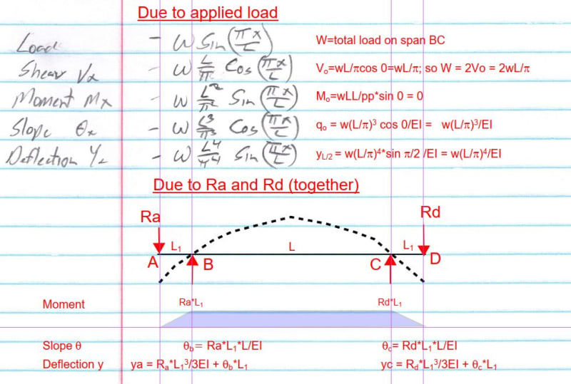
Hopefully this will explain what I have done. Let me know if there are any questions.

Capture_n8xrjj.jpg
 
BAretired:

I worked through the information contained in your most recent post and have attached your diagram with my notes. I used your equation for theta 0 due to Ra and Rb and added q0 from the applied load. Solving for Ra resulted in 1,711 lb. which does not equal the result of 3,214 lb. given to me from the beam deflection software. So I am still missing something.

I have also attached the beam deflection reports from the beam deflection software for the 2 and 4 reaction cases. As I have said above, I started this assuming this was a simply supported beam with supports at A and D. I developed the elastic line equations for this case using integration and the resulting spreadsheet model matches the 2 support beam deflection report exactly. So I am confident that my elastic line for 2 supports is correct.

After noticing that the deflections at the x = 6" and 68" locations in my elastic line model were greater than the clearance holes in the wall of the valve body, I realized that the shaft seals had to be acting to support the shaft. Otherwise we should see evidence of the shaft rubbing against the valve body out in the field, which we haven't.

So I ran the 4 support case in the beam deflection software which resulted in reactions Ra & Rd = -3,214.236 lb. and reactions Rb & Rc = 4,848.263 lb. I assume the reactions from the beam deflection software are correct.

I am now trying to update my spreadsheet model to give me the results that match the beam deflection software. I thought this would not be difficult and could be done using superposition to solve for the reactions for the statically indeterminate case. I has proven to be more difficult than I had anticipated. Perhaps I should go back to integrating to find the elastic line for 4 support case.

Any assistance you may be able to offer will be appreciated.

P.S. It seems that Eng-Tips will only allow one attachment per post. I will send the 2 and 4 support beam analysis software reports in two additional posts below.

 
 https://files.engineering.com/getfile.aspx?folder=7447daa4-21f9-43d6-a4cf-e1d075f28c93&file=Response_to_BAretired_Post_24_Sep_24_01-00.pdf
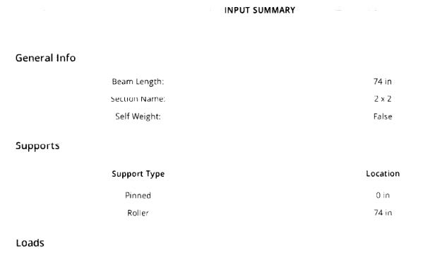
Check the input of your software. On the first page, I see the following:
Capture_v1fepk.jpg


The moment of inertia you gave me earlier was 0.785 which would be correct for a 2" diameter beam. It is not correct for a 2x2 beam. The span B-C was 62", not 74".

Check all of the input data! That should have been the first thing you did!
 
BAretired:

I noticed that and thought something was amiss but checking page 5 a 2" round cross section is shown.

Thanks,
 
Some Observations:
1. Your derivations for a sinusoidal load are all missing the integration constants which would be solved by applying the relevant boundary conditions.
2. I can vouch for the SkyCiv analysis being correct for the inputs noted in the printed software output.
3. Is your "beam" in fact a hollow pipe? If so that invalidates the skyciv analysis as it used a 2" diameter solid section.
4. I believe above you noted that the internal supports you want to act more like springs, you'll need some way to come up with a spring stiffness to use in the software. (though reading more into it sounds like it should really be a non-linear spring that approaches rigid after compressing the seals enough)

5. The more I see being added to describe your actual situation the more it feels like you are asking the wrong folks and using the wrong software, this is sounding like something better suited for inventor or adina.
 
Celt83 said:
BA[/color]]Some Observations:
1. Your derivations for a sinusoidal load are all missing the integration constants which would be solved by applying the relevant boundary conditions. Could be. I'm a little rusty on my integration, but I thought all of the constants turned out to be zero.
2. I can vouch for the SkyCiv analysis being correct for the inputs noted in the printed software output. Could be?
3. Is your "beam" in fact a hollow pipe? If so that invalidates the skyciv analysis as it used a 2" diameter solid section. 2" diam. solid bar is correct.
4. I believe above you noted that the internal supports you want to act more like springs, you'll need some way to come up with a spring stiffness to use in the software. (though reading more into it sounds like it should really be a non-linear spring that approaches rigid after compressing the seals enough) Maximum moment is not in agreement even for a simple span, although with 74" span, we are close.

5. The more I see being added to describe your actual situation the more it feels like you are asking the wrong folks and using the wrong software, this is sounding like something better suited for inventor or adina. Could be...I dunno.
 
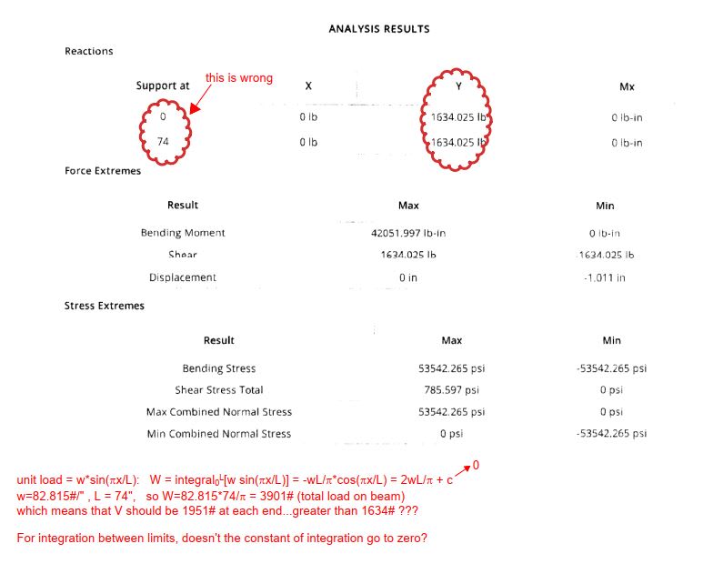
If we just consider a single span of 74" (even though that is incorrect), what is wrong with the text below?

Capture_fwsurd.jpg
 
BA:
"I'm a little rusty on my integration, but I thought all of the constants turned out to be zero."
you are correct I did not download the earlier PDF and thought the derivation was for the Sin load applied partially to a span not to a full simple span.
 

Part and Inventory Search

Sponsor