Continue to Site

Eng-Tips is the largest engineering community on the Internet

Intelligent Work Forums for Engineering Professionals

  • Congratulations KootK on being selected by the Eng-Tips community for having the most helpful posts in the forums last week. Way to Go!

Statics-beam total deflection 5

Status
Not open for further replies.

ntw88

Mechanical
Mar 13, 2020
6
I have forgotten my statics class.


Ultimately I am trying to determine Critical Speed of a shaft supported by two bearings with loads on each end. I am struggling with correctly calculating the total deflection in the beam. We have several calculators and they all give different results so I am tasked with building a new one that yields correct results that we can agree on and stand by. The situation as shown in the picture has a round shaft of length (A+B+C+D+E=L) supported by two bearings. Bearing G is fixed, and bearing H is an expansion (can move left and right slightly). The shaft has a uniform load w (its weight). It also has two forces acting on it, Fb and Fa. if it helps it is a steel shaft, but we use a variety of steels and various temperatures so the modulus may change.


if someone can solve this for total deflection and show their work so I can follow along and apply it to our applications I would greatly appreciate it. I have been mulling over this for days and cant seem to remember how to correctly do this.
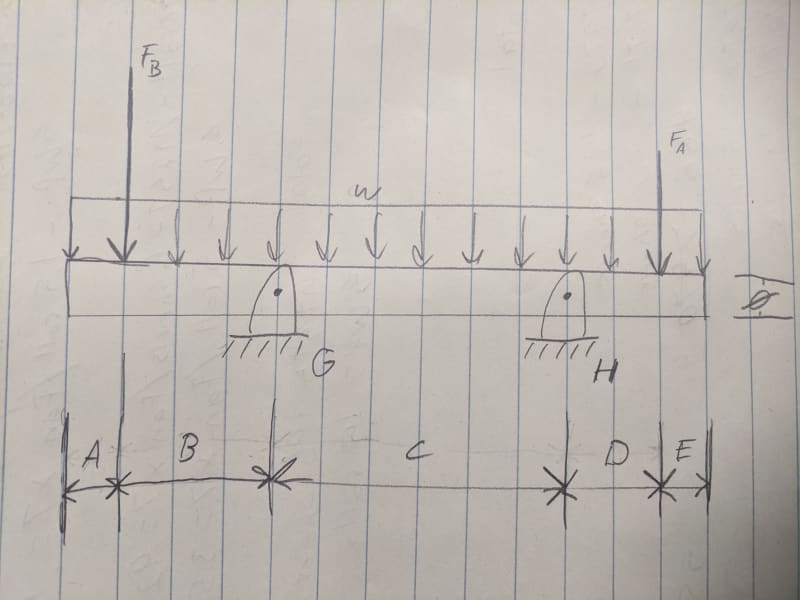
IMG_20200313_165748_ap5f1v.jpg
 
Replies continue below

Recommended for you

Hello,

Have you tried SkyCiv.com? They have some free beam calculators that will generate shear moment diagrams. If you need deflection, you can pay by the month for expanded capabilities.

Kyle
 
Find a picture in machinery's handbook that looks right and fill in the blanks. You can superimpose cases. The beam recipes are at about page 240 or so.
 
Ok, I'll pose my question differently …
If you don't have the knowledge to understand the principles involved, how do you have confidence to use tables based on these principles, particularly when you don't understand the limitations and caveats embedded in those tables ?

How can you confidently go to your boss and say "the structure is good ('cause the critical speed exceeds the requirements)" when your source is "something I found on the internet" ?

Yes, people are trying to help you, but do you even understand what "d2y/dx2=M/EI" means ?
btw there's a typo in there (should be d2y/dx2=M(x)/EI) and there is an implicit assumption (ie, I constant).

IMHO you should be able to pick up a text and solve the problem from first principles. But then I'm an "ass-hat".

another day in paradise, or is paradise one day closer ?
 
Machinery handbook - 29th edition - Oberg-Jones-Horton-Ryffel Page 197-198
 
I have recently purchased a copy this -
It is cheap < $25.

I have not had the time to check against a benchmark. It handles multiple load cases, calculates natural frequencies, allows complex shaft geometries, etc. Response from question posed was within a couple of hours.
 
As Tmoose, dvd and others hinted, the critical speed problem will ultimately go quite a bit beyond the problem you're trying to solve.

First things first though, the natural frequency of a mechanical structure is independent of the external (non-inertial) forces acting on it. So your belt load shouldn't be relevant to any simple (linear) critical speed calculation! (*) Take it out of your problem.
[ul]
[li]* ok, it might be relevant if you had a sophisticated model including load-dependent properties of sleeve bearing stiffness or damping, but that's not what you're doing here.
[/li]
[/ul]
I assume you are going to end up using the deflection at location of the fan and use that together with fan mass to estimate a natural frequency? That may be a useful theoretical exercize as a first step in thinking about the problem (after you have removed the force of the belt). But please recognize it will ignore a number of other factors:
1 - gyroscopic effects of fan wheel (adding them to your model will make first estimated critical speed increase).
2 - non-infinite stiffness at/below the bearing (adding that to your model will make estimated first natural frequency decrease)
3 - distributed mass of shaft. (adding that to your model will make estimated first natural frequency decrease). Or if you are using the static deflection shape to determine mode shape assumption for Raleigh's method, maybe you are planning to include this in your kinetic energy term, in which case you have mostly accounted for this item, other than its minor effect on modeshape assumption.
4 - this list is not all-inclusive. 1 and 2 are the potential biggest hitters imo, 3 is often relatively minor. Many of the others are difficult to know (characteristics of the fit of the fan wheel onto the shaft).

As mentioned, you may need account for steps in shaft diameter.

Estimating critical speeds is usually not an easy thing. Often people resort to numerical methods when direct measurements can not be made. But I'm not trying to discourage you ... using simpler analytical methods also helps develop intuition and sometimes you can analyse the likely effects of your simplifying assumptions to see which can be reasonably excluded for the particular problem you're considering or to bound the direction of the error in your estimate.
=====================================
(2B)+(2B)' ?
 
Status
Not open for further replies.

Part and Inventory Search

Sponsor