Continue to Site

Eng-Tips is the largest engineering community on the Internet

Intelligent Work Forums for Engineering Professionals

  • Congratulations SSS148 on being selected by the Eng-Tips community for having the most helpful posts in the forums last week. Way to Go!

Statics or FEA required? Frame Drawing in Post 5

Status
Not open for further replies.

P1ENG

Structural
Aug 25, 2010
237
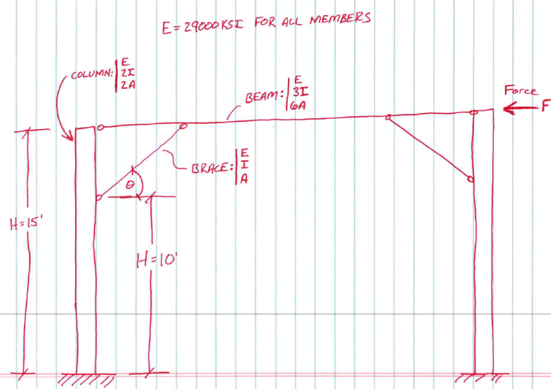
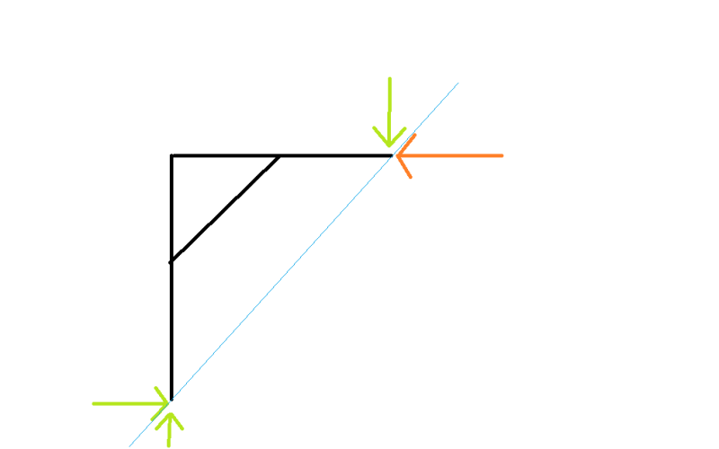
I am trying to calculate the brace force of the attached frame. I can do it easily in RISA, but I want to incorporate it into a MathCAD calculation because it will be easier and faster to produce a calculation set for future projects. I've been racking my brain to figure it out because I know the stiffness of each element affects the load that the brace sees. So, I tried to simplify the properties of the members in the attached. The brace has the weakest moment of inertia and and cross-sectional area, I and A respectively. I then made the other members have arbitrary factors of I and A. The column is fixed to the foundation. The beam and braces have pinned ends. I showed the force outside the one column, but it is actually at the center of the beam (diaphragm load) so it loads each brace equally.

So am I stuck using RISA for each frame that comes up or can someone provide a (maybe not simple, but shortish) method of calculating by hand?

2_i6tdb8.png


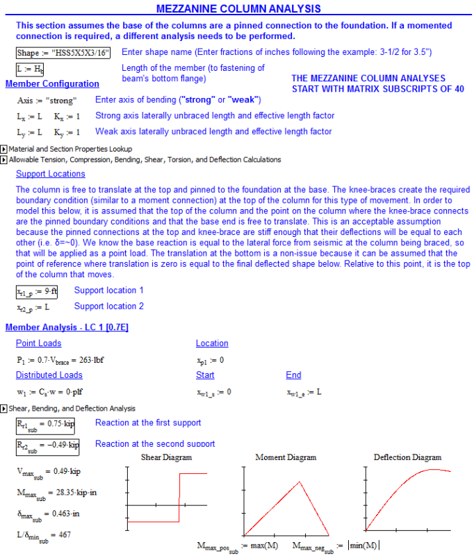
On a related note, if the base of the column is pinned, I did an "equivalent" analysis of the column as a beam with pinned supports at the beam and brace and a point load (equal to 1/2 the force) at the foundation which is assumed the free end. This works with the assumption that the translation at the brace and beam are equal. This is not exactly true, but because of the stiffness of the members and close proximity of the two points, ends up pretty close. The pinned base requires a stiffer column to keep the drift down, hence my attempt at the above.

Juston Fluckey, SE, PE, AWS CWI
Engineering Consultant
 
Replies continue below

Recommended for you

There is no direct solution to a redundant structure such as this. You have to use a stiffness or flexibility method or some form of those, using classical analysis methods (moment distribution, slope deflection, moment area, etc.)

Check out Eng-Tips Forum's Policies here:
faq731-376
 
I think you need to include the fixed end moments at the base. This is more natural than assuming pinned columns (which means the horizontal beam is doing a lot of bending, though easier to solve ... simple three force problem).

I think you can simplify the problem if the structure is symmetrical (which it looks to be).

As drawn it looks triply redundant (6 reactions, 3 equations) ... not impossible to solve by hand but a bit of a slog. I like the unit force method. Using symmetry reduces this to doubly redundant ... much easier.

Maybe solve the symmetrical case first, then generalise ?

another day in paradise, or is paradise one day closer ?
 
You can get an approximate moment diagram pretty easily and then use that to figure out your forces. Solve the frame problem with fixed beam to column connections and no knee brace. Draw your moment diagram.

Now draw in your knee brace. At the point where your knee brace intersects with your beam, the moment diagram can be modified to go from a peak at the knee brace intersection to zero at the end of the beam. Do the same thing on the column.

This implies certain vertical and horizontal forces in the brace. Back calculate the forces required to create the moment diagram.

You can obviously do this in numbers. I just think it's easier to visualize with the moment diagram.

This becomes less true to reality the further into your span the knee brace projects, because the stiffness assumptions in your frame analysis become questionable.
 
rb1957 said:
I think you need to include the fixed end moments at the base.
The base on some of these columns are not a (4) bolt pattern because of their placement against walls. They are plates extended to one side of the tube column with (2) bolts. I don't know if there is a typical name for such a base plate type, but I know it is common. That is why I was assuming pinned connections because that type of base is only good for a moment in one direction unless I super beef the plate to take the bending and eliminate (or calculate) the prying action. Which is very doable I suppose.

^ My thought process was progressing as I was typing and I walked my self through to that conclusion. I never learned the unit force method. By education, I am an ME and we only used Singularity Functions which I attempted to incorporate into this problem. I also tried reducing the beam, brace, and column into spring constants but that was getting me deep into math I couldn't handle last night.

TLH said:
I just think it's easier to visualize with the moment diagram.
I know the shape of the moment diagram, but that doesn't help me determine my numbers unless I know the actual moment at the brace intersection, which I don't know unless I have that brace force I am trying to figure out.

Juston Fluckey, SE, PE, AWS CWI
Engineering Consultant
 
If you can call the column bases pinned, I think that you can look at half the structure with half the load on it and a pin/horizontal roller at the middle of the beam.

I like to debate structural engineering theory -- a lot. If I challenge you on something, know that I'm doing so because I respect your opinion enough to either change it or adopt it.
 
If you call the structure pinned, I'd make sure the pin can accomodate the rotation you're expecting
 
if the columns are pinned, it becomes a simple three force problem; statically determinate.

but you also said you wanted to address the general solution "for future projects".

btw, isn't prying the moment reaction ? ("unless I super beef the plate to take the bending and eliminate (or calculate) the prying action") if the flange is flexible then no prying, if the flange is stiff then there is a moment reaction (evidenced by the prying).

sorry, but I have to add "who's prying now" ?

another day in paradise, or is paradise one day closer ?
 
rb1957: Prying is for a momented reaction. I was talking myself into your suggestion. If I want to consider the (2) bolt base plate as a moment connection, I need to look at the prying action of the plate. Before that statement, I thought the plate would just bend/deflect, not putting any tension into the bolts thereby making it a pinned connection. I think I like the fixed end condition regardless of anchoring pattern, so I will provide both options in my analysis.

My approach will be to model the frame for a 1 kip lateral load and get the values from the RISA model and enter them into my calculation as a snapshot. I will make the beam extension as short as possible beyond the brace for the worst-case condition. Then I will just factor my model results by my actual lateral force divided by the 1 kip model value to get the values I need. I think this is easier than providing the RISA report at the end of my calculations. Example below which is my work in progress and I need to add snapshots for column shear, moment, and deflection diagram:
2_posfvp.png


I have no question on the pinned base condition:
1_zuxlg3.png


Juston Fluckey, SE, PE, AWS CWI
Engineering Consultant
 
not sure I get your reactions.

the FBD for the 1/2 frame is incomplete, as there is a moment in the horizontal on the CL.

The horizontal reaction is 1000 lbs; the vertical depends on the width (or 1/2 width of the frame).

I take it the knee brace reacts only axial load. The vertical component of the knee brace works with the load in the vertical (at the top) to create a couple reacting the mid-span moment, yes? So this component will be larger than the applied load, so the reactions at the LH end of the horizontal beam are both vertical and horizontal.

If you're trying for a general solution (in your Mathcad), avoid using fixed dimensions from the problem ... input all dimensions.


another day in paradise, or is paradise one day closer ?
 
rb1957:
I am being conservative. Yes, the length of the frame matters, but the shortest length is worst-case. I put a vertical boundary at the right end of the beam (sorry, it wasn't shown). I don't need to put a moment boundary condition there because it is either a symmetric frame or the other end only has a pinned column with no knee brace. My only goal is to get the maximum axial load (yes, axial only member [the circles at the ends of the members indicate pinned condition]), which the model is doing. I will then check my beams and columns elsewhere in the calculation using the axial load in the brace (with my beloved singularity functions). Because my frame is actually longer than the model, I will always be conservative with the load I apply to the beams and columns.

Yes, I have both horizontal and vertical reaction at the left hand end of the beam, but that can be calculated from the axial load of the brace. I'm trying to reduce the information I need to pull from the model results. Really, all I need is the brace force and I can calculate everything else.

Juston Fluckey, SE, PE, AWS CWI
Engineering Consultant
 
"I don't need to put a moment boundary condition there" ... you're right ... the 1/2 frame is a two force problem, which shows there's shear in the horizontal (and this is how the couple to react the offset moment is developed between the two ground reactions).

the knee brace load carries the equivalent moment (ie if you had a fixed connection between vertical and horizontal you wouldn't need a knee brace, in the absence of a fixed connection the moment is reacted as knee_brace_load * distance_to_frame_corner).

I think this is what your FBD should look like ...
Untitled_siu8b1.png


another day in paradise, or is paradise one day closer ?
 
Mathcad can easily deal with matrix calculations. FEA is basically solving a set of simultaneous equations. You can do that with matrices and Mathcad.
 
I have set the frame up in my frame analysis spreadsheet (attached), which will allow you to play with different dimensions etc and get a very quick result. I have used metric units, but you can use any consistent unit system. To change the frame dimensions, just enter the coordinates in the bold cells on the Input1 sheet, then click recalculate on the output sheet.

Input, deflected shape plot, and bending moments for 100 kN applied load are shown below.

Results should of course be checked with an independent calculation or software.

URL]


URL]


URL]


Doug Jenkins
Interactive Design Services
 
Though it's fun and interesting to discuss and debate, it seems like you're doing a lot of work and head-scratching just to avoid using a program that's already designed to do what you want it to do... and also has infinitely more flexibility if the next job has some assumption that doesn't quite fit those of your "hand calc". I'd personally just recommend setting up frame in RISA that has everything set up and then all you have to do is go open that "template" file for each job and adjust some coordinates and loads, hit solve, and print.

Sorry... just my two cents as a partner in a firm where I watch my partners waste countless hours doing things like this by hand to "avoid RISA" models that I could have done in 1/10th the time using RISA.
 
IDS has a nice drawing, you should be able to see from that, that you can approximate it to a 3 member frame with all 4 joints fixed, and then draw a free body diagram for each corner taking the boundary conditions for the beams from the 3 beam model.

Cheers

Greg Locock


New here? Try reading these, they might help FAQ731-376
 
I agree 100% with ARKeng.

Check out Eng-Tips Forum's Policies here:
faq731-376
 
ARKeng/JAE,
If this were a one-off project, I wouldn't hesitate to model the whole thing in RISA. However, in the long run, this will save me a lot of time. This should be a repeat client and this method will make it faster to produce (10) sets of calculations rather than (10) sets of calculations and models. I don't like to waste time, but I do admit I can get sidetracked with math. But once that math is done, I can use it multiple times in the future. There is a trade-off though. I'm not going to spend the next 5 days trying to make the math work. I could never recover that time. I'm at a happy medium.

ARK: care to explain the handle? Are they initials or were you involved with the ARK project?

IDS,
Thanks for the spreadsheet, however it doesn't look like any analysis methods are visible to the user. I could accomplish the same thing using RISA, which I was trying to avoid.


Juston Fluckey, SE, PE, AWS CWI
Engineering Consultant
 
PIEng - there is nothing built in, but the advantage of a spreadsheet is you can insert a sheet(s) and set it up to generate the node coordinates and section properties automatically, and generate whatever output information you want. For instance, knowing the forces, moments and deflections at each node, it would be pretty easy to check that they satisfy equilibrium and strain compatibility, and use that as the check on the output.

Doug Jenkins
Interactive Design Services
 
ARKeng said:
Sorry... just my two cents as a partner in a firm where I watch my partners waste countless hours doing things like this by hand to "avoid RISA" models that I could have done in 1/10th the time using RISA.

Seriously. I would have had the answer to that in my 25 year old 2-D frame program in less time it took to type the original post.
Time is money in this business.
 
Status
Not open for further replies.

Part and Inventory Search

Sponsor