Continue to Site

Eng-Tips is the largest engineering community on the Internet

Intelligent Work Forums for Engineering Professionals

  • Congratulations IDS on being selected by the Eng-Tips community for having the most helpful posts in the forums last week. Way to Go!

Steel Beam Bearing - ASIC J10.4 Web Sidesway Buckling 5

Status
Not open for further replies.

RFreund

Structural
Aug 14, 2010
1,881
I am trying to clarify J10.4 in AISC - Web Sidesway Buckling. I might be a little picky here, but I want to make sure I understand this correctly.
AISC gives two different equations depending on whether or not the compression flange is restrained against rotation. Here is my confusion:

J10.4 -
"This section applies only to compressive single-concentrated forces applied to mem-
bers where relative lateral movement between the loaded compression flange and the
tension flange is not restrained at the point of application of the concentrated force."

J10.4a
"If the compression flange is restrained against rotation"
J10.4b
"If the compression flange is not restrained against rotation"

"When the required strength of the web exceeds the available strength, local
lateral bracing shall be provided at both flanges at the point of application of the
concentrated forces."

Comm J10.4
"The web sidesway buckling provisions (Equations J10-6 and J10-7) apply only to
compressive forces in bearing connections and do not apply to moment connections.
The web sidesway buckling provisions were developed after observing several unex-
pected failures in tested beams (Summers and Yura, 1982; Elgaaly, 1983). In those
tests, the compression flanges were braced at the concentrated load, the web was sub-
jected to compression from a concentrated load applied to the flange, and the tension
flange buckled (see Figure C-J10.2)."

Comm J10.4a
"For flanges restrained against rotation (such as when connected to a slab), when.."

Comm J10.4b
"For flanges not restrained against rotation, when"

Alright, so my questions:
[ol 1]
[li]In my first snippet AISC states this limit states only applies to beams where relative lateral movement between flanges is not restrained. However, Figure C-J10.2 (or J10.3 depending on edition) defines the unbraced lengths used in the web sidesway buckling equations. The last figure shows the top and bottom flange braced at the location of the concentrated load and defines the unbraced flange length as L/2. Shouldn't the limit state not apply?[/li]
[li]AISC states for flanges "restrained against rotation", do they mean - the local compression flange is restrained against rotation or the entire section is restrained against rotation? Or do they mean that the compression flange is restrained against lateral translation? In figure CJ10.1 they show the compression flange as being braced against lateral translation. Also in the commentary they state "(such as when connected to a slab)".[/li]
[li]Would this apply to the end of a uniformly loaded beam? I want to say no, because it states the "loaded compression flange". In the case of the end of a beam, you would have a "loaded tension flange".[/li]
[/ol]

Thanks!

EIT
 
Replies continue below

Recommended for you

In my first snippet AISC states this limit states only applies to beams where relative lateral movement between flanges is not restrained. However, Figure C-J10.2 (or J10.3 depending on edition) defines the unbraced lengths used in the web sidesway buckling equations. The last figure shows the top and bottom flange braced at the location of the concentrated load and defines the unbraced flange length as L/2. Shouldn't the limit state not apply?

The way I read it, the limit state still applies because the buckling can happen away from the brace point. I've always (conservatively) taken it that way.

AISC states for flanges "restrained against rotation", do they mean - the local compression flange is restrained against rotation or the entire section is restrained against rotation? Or do they mean that the compression flange is restrained against lateral translation? In figure CJ10.1 they show the compression flange as being braced against lateral translation. Also in the commentary they state "(such as when connected to a slab)".

Effectively such a connection can do both. (You'd have to fall back on their definition in the bracing section of the code.)

Would this apply to the end of a uniformly loaded beam? I want to say no, because it states the "loaded compression flange". In the case of the end of a beam, you would have a "loaded tension flange".

No. I've never seen it apply for a distributed load. Just concentrated. (At least for rolled shapes. Can't remember for plate girders.)
 
RFreund said:
The last figure shows the top and bottom flange braced at the location of the concentrated load and defines the unbraced flange length as L/2. Shouldn't the limit state not apply?

Correct, it should not apply. I believe this to be a misprint unless I just don't understand what web sway buckling is at all. Additionally, if the diagram isn't a misprint, then J10.4 would have to be because it pretty explicitly says that this limit state does not apply when relative flange translation is prevented at the point of load application.

Rfreund said:
AISC states for flanges "restrained against rotation", do they mean - the local compression flange is restrained against rotation

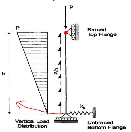
They mean that, and only that. The two cases covered are based on derivations where the web is treated as a column with a lateral spring support at the bottom as represented by the lateral flexibility of the bottom flange. One of the cases treats the faux column as pinned/pinned; the other treats it as fixed/pinned. The fixing happens at the compression flange when it is restrained rotationally.

RFreund said:
Would this apply to the end of a uniformly loaded beam?

It's a moot point as your uniformly loaded beam must have rotational restraint at the supports. Let's consider a point loaded cantilever instead as that would seem to be a more salient example (loaded on the tension flange and not necessarily braced against relative flange translation. I would say that web sway buckling would apply here simply because nothing would seem to be different about the mechanics. My guess is that the spec language drifted into implying that this check only applies when the compression flange is loaded because:

a) that represents the overwhelming majority of the cases and;
b) in the other cases, regular LTB would normally dominate behavior I suspect.

I like to debate structural engineering theory -- a lot. If I challenge you on something, know that I'm doing so because I respect your opinion enough to either change it or adopt it.
 
[blue] (Kootk) [/blue]

Correct, it should not apply. I believe this to be a misprint unless I just don't understand what web sway buckling is at all. Additionally, if the diagram isn't a misprint, then J10.4 would have to be because it pretty explicitly says that this limit state does not apply when relative flange translation is prevented at the point of load application.

I've always taken it as it still should apply because Figure C-J10.2 doesn't show the ends (i.e. clip angle connections) as being braced points. (With the little "x"'s.) We take them as such for LTB calculations.....but I've never been too sure as far side sway buckling goes. In the tests I have seen for this, they typically have used stiffeners at the ends to preclude it and/or rotational restraint of the flanges at those ends. (Clip angles don't do that.)

J10.4 may sound like it's precluding the ends since it is not "the point of application"....but if the beam is long enough.....does that really matter? The "point of application" is anywhere with a high shear and a long unbraced length.

All this is among the many reasons that I typically size a beam to preclude side sway buckling (by cutting down on the unbraced length). I've never been 100% sure where and when it will happen. (And if a single stiffener will address it.)


WARose said:
The "point of application" is anywhere with a high shear and a long unbraced length.

This statement would be the crux of our differing opinions. I believe it to be incorrect. My understanding is that the instability being addressed arises from the eccentricity between an external load applied to the flange and the internal shear resisting it. As the unloaded flange and the lower part of the web displace laterally relative to the loaded flange, P-delta rears its ugly head yet again. When you have only internal shear and no nearby external load, all of the forces at a given cross section move along with the cross section and there's no eccentricity or P-delta induced.

WARose said:
I've always taken it as it still should apply because Figure C-J10.2 doesn't show the ends (i.e. clip angle connections) as being braced points.

My thoughts on this are an outgrowth of my comment above. I've always thought that they chose to show clip angles in those diagrams because they specifically wanted to avoid implying a sway buckling condition at the ends of the beams. Clip angles transmit the beam reactions as web shear in a way that obviates the sway buckling checks in my estimation. Of course, we're both just making inferences about somebody else's sketch and it's natural for us to each view that in ways consistent with our own beliefs.

WARose said:
In the tests I have seen for this, they typically have used stiffeners at the ends to preclude it and/or rotational restraint of the flanges at those ends. (Clip angles don't do that.)

Clip angles don't restrain flange rotation but, then, I would argue that they wouldn't need to in order to prevent sway buckling. At least not as long as they're full depth or close to it. The flange rotational restraint business is about utilizing the web as a cantilever down from the loaded flange to the unloaded flange. That becomes a means of preventing relative lateral displacement between the flanges. A full depth clip angle, like discrete nodal bracing, accomplishes that goal outright and, as such, the flange rotational restraint business falls by the wayside.

I like to debate structural engineering theory -- a lot. If I challenge you on something, know that I'm doing so because I respect your opinion enough to either change it or adopt it.
 
Good thoughts Kootk (although I still disagree about the ends).

I think I'm going to send a e-mail to AISC's Steel Solutions Center to get their input. [EDIT: Sent off the the e-mail....will advise on the reply I get.]

The last AISC Journal article I read on this (i.e. 'Sidesway Web Buckling of Steel Beams', by: Grondin & Cheng, 4th quarter 1999, p.169-179) while saying that AISC's provisions on sidesway web buckling were very conservative concluded the article this way: "Further investigation of beams with end rotational restraint is required." I wasn't sure if that was to be able to milk more capacity out of the equations they proposed (which were not as robust as AISC's) or what.
 
What I find especially interesting is that tension chord bracing demand in trusses (Link) is a nearly perfect analog for web sway buckling in wide flange beams. I dig that. Truth should have an element of universality to it. And I believe that there are shared insights. It's near the diagram below where Fisher gets into describing how the stability demand probably only occurs at applied loads and not between them. That, in part, informs my belief that the same is true for wide flange beams.

c01_agkga9.jpg


I like to debate structural engineering theory -- a lot. If I challenge you on something, know that I'm doing so because I respect your opinion enough to either change it or adopt it.
 
[blue](RFreund)[/blue]

Let me know what they have to say.

Will do.

I was looking at the 13th edition earlier today and thinking more about it...and one thing I noticed that lent credence to my "anywhere" theory (under the right conditions) was the wording of Sections J10.4.a & J10.4.b.

in (a) (for the case of If the compression flange is restrained against rotation) it says:

"When the required strength of the web exceeds the available strength, local lateral bracing shall be provided at the tension flange or either a pair of transverse stiffeners or a doubler plate shall be provided."

in (b) (for the case of If the compression flange is [red]not[/red] restrained against rotation) it says:

"When the required strength of the web exceeds the available strength, local lateral bracing shall be provided at both flanges at the point of application of the concentrated forces."

Note the difference: in the latter (more unrestrained) condition, the addition of [red]single[/red] group of stiffeners will not do the job. In other words: buckling could likely be a problem elsewhere in the beam with the unrestrained compression flange (and long enough unbraced length).

In conclusion: I feel that the intro to J10.4 is just not worded right......and under the right conditions, this buckling can happen elsewhere in a beam (aside from the point of application or a end bearing).

It may be (like Kootk says above), you'd have problems with other modes of failure before this would control at those points (which might explain the provisions I mentioned in another post for testing (i.e. additional stiffeners)).....but this is speaking strictly of sidesway buckling.
 
I think WARose is on the right track. My take is that the introductory paragraph of Section J10.4, as currently written, is misleading in that it implies an oversimplification that does not match the Specification requirements. The (h/tw)/(Lb/bf) ratio should be calculated and compared to the respective limiting value (2.3 if the compression flange is restrained against rotation and 1.7 if the compression flange is not restrained against rotation) and only then can one make the determination that web sidesway buckling does, or does not, apply. Put another way, with the 'right' cross-section geometry, the tension flange could buckle to the left or right of a single tension flange brace point. The unbraced flange lengths indicated in Figure C-J10.2 are correct, in my opinion.
 
WARose said:
Note the difference: in the latter (more unrestrained) condition, the addition of single group of stiffeners will not do the job. In other words: buckling could likely be a problem elsewhere in the beam with the unrestrained compression flange (and long enough unbraced length).

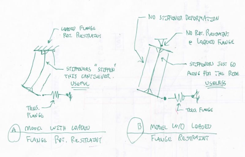
With love, I'm pretty sure that you're interpreting that bass ackwards. They're not saying that you should add more stiffeners when there is no rotational restraint at the loaded flange. Rather, they're saying that, sans rotational restraint to the loaded flange, stiffeners are utterly useless at any location and a zillion of them wouldn't make a lick of difference. In support of this I submit:

1) Last sentence of the AISC commentary blurb below. Note that I consider quoting the opinions of other people/organizations to be a relatively weak form or proof. Weak... but not quite nothing.

2) Sketch below showing the difference between the restrained and unrestrained cases highlighting why stiffeners are useless at any location when the rotational restraint to the loaded flange is absent.

@WARose: since we've both read the same papers, I assume that this is old hat to you. And I certainly don't want to condescend (at least not any more than usual). That said, I want to be sure that we're on the same page on this as there's not much basis for discussion here if we have any disagreement on this fundamental aspect of behavior. I also thought that the sketches might be of interest to any lurkers that might be following along.

c01_u8hve7.jpg


c01_dpk0ck.jpg


I like to debate structural engineering theory -- a lot. If I challenge you on something, know that I'm doing so because I respect your opinion enough to either change it or adopt it.
 
I've got a couple more hours here before Easter weekend swallows me whole. I'm going to use it to get some more ideas on the table for further discussion.

c01_zofaqz.jpg


WARose said:
I feel that the intro to J10.4 is just not worded right......and under the right conditions, this buckling can happen elsewhere in a beam (aside from the point of application or a end bearing)

Hokie said:
My take is that the introductory paragraph of Section J10.4, as currently written, is misleading in that it implies an oversimplification that does not match the Specification requirements.

Note that if one adopts my view of things, every word of that opening paragraph rings succinctly true. Just sayin'...

I do take issue with the way that things are presented further along in J10.4 though. As I see it, things should read:

IF [proportions exceeded] THEN

[check web for buckling as a column between laterally stationary flanges]​

ELSE

[check side sway buckling per blah blah..]​

END IF

Unfortunately, they don't bother to tell you what the first check, for web column style buckling, is. Presumably that's covered by web yielding, crippling, and buckling in the other provisions of chapter J. Still though, it's confusing that they don't just come out and say it. I also think that it would be clearer if they just did away with the proportion ratio stuff and just said "hey, check sway along with all the other stuff and see what governs". Easy peasy. Seems to me that they're trying to save us a little math when certain proportions are met but sacrificing clarity of intent in the process. Fail.

I like to debate structural engineering theory -- a lot. If I challenge you on something, know that I'm doing so because I respect your opinion enough to either change it or adopt it.
 
WARose said:
Good thoughts Kootk (although I still disagree about the ends)

Hokie said:
with the 'right' cross-section geometry, the tension flange could buckle to the left or right of a single tension flange brace point.

I'll play my own devil's advocate for a moment and assume that sway buckling is possible at locations other than concentrated loads. Even at that, I know of two locations where it definitely won't happen:

1) Near the ends, assuming the usual condition of rotational restraint there and;
2) Near the concentrated load, assuming rotational restraint there.

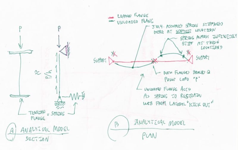
The reason for this is that the "spring" bracing the edge of the web opposite the load is really just the unloaded flange acting as a simple span girt. The consequence of that being that our spring is wickedly stiff near both the supports and the concentrated loads. So if "in the field" sway buckling is a thing, then it must really be occurring in the field, far away from supports and concentrated loads. I'll get into the field condition next.

Another point of interest here is that our code checks only address a single concentrated load occurring at mid-span. For single loads occurring at other locations, the checks would be conservative. For multiple loads, all relying on the same unloaded flange as the bracing "spring", the checks would be unconservative unless thoughtfully adapted to that situation.

c01_u633dw.jpg


I like to debate structural engineering theory -- a lot. If I challenge you on something, know that I'm doing so because I respect your opinion enough to either change it or adopt it.
 
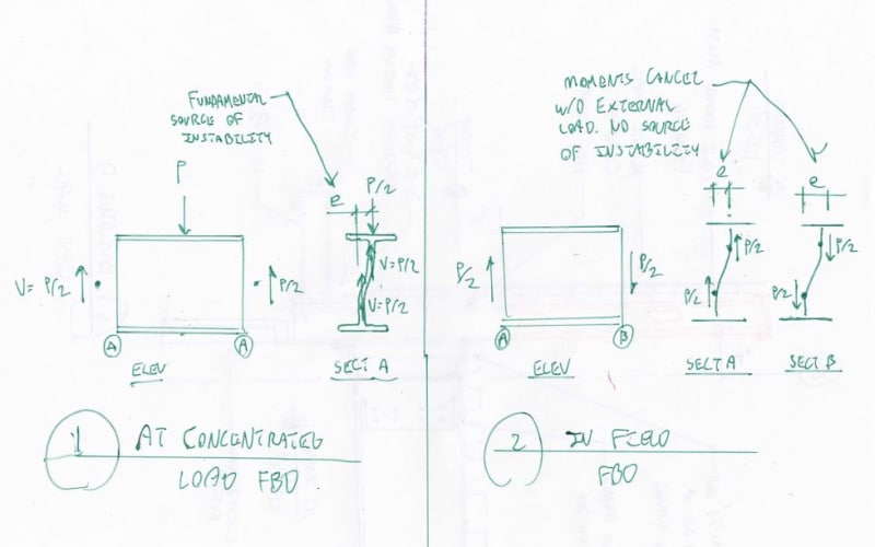
Regardless of what we or AISC have to say about things, I don't feel that there's any real "there" there unless it can be expressed as a valid free body diagram. Consequently, below, I've shown:

1) The case at a concentrated load, indicating a valid source of instability.

2) The case away from any concentrated loads, indicating the lack of a valid source of instability.

So I throw down this gauntlet as a challenge to those advocating sway buckling in the field: FBD it.

I say no external load = no sway buckling. The only non-local instability in the field that I see is wholesale rotation of the section about a point in space centered over the non-distorted web. And that's LTB which is another animal altogether.

c01_en7pvf.jpg


I like to debate structural engineering theory -- a lot. If I challenge you on something, know that I'm doing so because I respect your opinion enough to either change it or adopt it.
 
c01_k6jidn.jpg


Note that, in the commentary blurb above, they specifically exclude moment connections from consideration. Why? I contend that it's because a moment connection will deliver a tension force to the connection offsetting the destabilizing effect of the accompanying compression force. The net effect is that you end up with essentially the "#2 field" case that I showed above. No net external load = no sway buckling. One may want to rethink this "out" if you were attempting something silly like carrying a W36 column with a W6 beam.

I like to debate structural engineering theory -- a lot. If I challenge you on something, know that I'm doing so because I respect your opinion enough to either change it or adopt it.
 
c01_jcubpa.jpg


This blurb, also from the commentary, also provides some fodder. They make a special point of saying that the stiffeners must be designed to carry the full load. Why? Presumably the web has already passed yielding and crippling checks so the stiffeners aren't needed to carry the load, only to laterally stabilize the unloaded flange, right? Wrong. I contend that this statement was included because of this:

KootK said:
When you have only internal shear and no nearby external load, all of the forces at a given cross section move along with the cross section and there's no eccentricity or P-delta induced.

I believe that the stiffeners must carry the full load so that one can plausibly claim that, away from the stiffeners, all load is carried via beam shear and none is carried via residual, destabilizing web compression. Of course there will always be some web compression owning to compatibility but, as always, we do the best we can with what we've got at hand.

I like to debate structural engineering theory -- a lot. If I challenge you on something, know that I'm doing so because I respect your opinion enough to either change it or adopt it.
 
Quote (WARose)
Note the difference: in the latter (more unrestrained) condition, the addition of single group of stiffeners will not do the job. In other words: buckling could likely be a problem elsewhere in the beam with the unrestrained compression flange (and long enough unbraced length).

With love, I'm pretty sure that you're interpreting that bass ackwards. They're not saying that you should add more stiffeners when there is no rotational restraint at the loaded flange. Rather, they're saying that, sans rotational restraint to the loaded flange, stiffeners are utterly useless at any location and a zillion of them wouldn't make a lick of difference.

How is that possible though? If you added a "zillion" of them (say one every few inches) you don't have the same beam anymore. In fact sidesway web buckling should be completely precluded.

I think a far more likely explanation for J10.4.b. being worded that way is: to instruct someone as to when/where/how often to add those stiffeners would overly complicate things and wouldn't be practical. It is probably better in such a situation to just go back to the drawing board and cut down on the unbraced length.

Now, regarding your pic "B" in your reply of 31 Mar 18 20:08.......you say that "the stiffeners just go along for the ride-useless". Again: if this theoretical beam had a pile of stiffeners every few inches......how could it buckle at all from sidesway like that? Any buckling seen would be from another mode. (I.e. LTB, etc.) You would essentially have a HSS with a lot of holes in the side.....the web couldn't buckle from sidesway.

Note that if one adopts my view of things, every word of that opening paragraph rings succinctly true. Just sayin'...

I do take issue with the way that things are presented further along in J10.4 though. As I see it, things should read:

IF [proportions exceeded] THEN

[check web for buckling as a column between laterally stationary flanges]

ELSE

[check side sway buckling per blah blah..]

END IF

At least we are in agreement it could be worded better. [smile] Doesn't fit either of our interpretations.


WARose said:
How is that possible though? If you added a "zillion" of them (say one every few inches) you don't have the same beam anymore. In fact sidesway web buckling should be completely precluded.

As I see it, "web sway bucking" is any form of relative lateral displacement between flanges resulting from a local, column like instability in the web. That would consist of:

1) The S-shaped web distortion that we generally like to visualize/test.

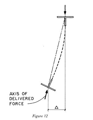
2) Straight up rotation of the beam as a rigid cross section (sketch below).

Number two, of course, is not prevented by stiffeners, tightly spaced or otherwise. In support of this conception of sway buckling, consider that the code capacity of the member for the unrestrained case doesn't actually depend on t_w. I believe that is because web distortion, and thus stiffener involvement, is not a factor in the unrestrained case.

WARose said:
Any buckling seen would be from another mode. (I.e. LTB, etc.)

Yeah, since both LTB and sway may produce a roll in the member, the waters get muddied some with respect to our observations and conceptual visualizations of the outcome. LTB, constrained axis LTB, and web sway buckling surely start to overlap with regard to look and feel and may only be distinguishable based on the different origins of instability for the various modes.

c01_hrwjcf.jpg


I like to debate structural engineering theory -- a lot. If I challenge you on something, know that I'm doing so because I respect your opinion enough to either change it or adopt it.
 
[blue](Kootk)[/blue]

As I see it, "web sway bucking" is any form of relative lateral displacement between flanges resulting from a local, column like instability in the web. That would consist of:

1) The S-shaped web distortion that we generally like to visualize/test.

2) Straight up rotation of the beam as a rigid cross section (sketch below).

Number two, of course, is not prevented by stiffeners, tightly spaced or otherwise. In support of this conception of sway buckling, consider that the code capacity of the member for the unrestrained case doesn't actually depend on t_w. I believe that is because web distortion, and thus stiffener involvement, is not a factor in the unrestrained case.

Actually it does (at least in the 13th edition). Equations J10-6 (i.e. compression flange restrained against rotation) and J10-7 (i.e. compression flange not restrained against rotation) both have web thickness as a variable.

[blue](Kootk)[/blue]

Yeah, since both LTB and sway may produce a roll in the member, the waters get muddied some with respect to our observations and conceptual visualizations of the outcome. LTB, constrained axis LTB, and web sway buckling surely start to overlap with regard to look and feel and may only be distinguishable based on the different origins of instability for the various modes.

To my mind, it's just about absolutely impossible for the web to buckle (in sidesway) with a large number of stiffeners present. If the minimal forces required to restrain the beam at the point of application were present at the ends (and the beam had any rotational stiffness at all)....it just shouldn't happen. I think J10.4.b is worded that way because there is no point in doing a research project for a beam design. For all practical purposes.....it's time to pick a new size if you run into this. (Rather than placing a pile of stiffeners.)
 
Status
Not open for further replies.

Part and Inventory Search

Sponsor