Continue to Site

Eng-Tips is the largest engineering community on the Internet

Intelligent Work Forums for Engineering Professionals

  • Congratulations IDS on being selected by the Eng-Tips community for having the most helpful posts in the forums last week. Way to Go!

Steel Beam Bearing - ASIC J10.4 Web Sidesway Buckling 5

Status
Not open for further replies.

RFreund

Structural
Aug 14, 2010
1,881
I am trying to clarify J10.4 in AISC - Web Sidesway Buckling. I might be a little picky here, but I want to make sure I understand this correctly.
AISC gives two different equations depending on whether or not the compression flange is restrained against rotation. Here is my confusion:

J10.4 -
"This section applies only to compressive single-concentrated forces applied to mem-
bers where relative lateral movement between the loaded compression flange and the
tension flange is not restrained at the point of application of the concentrated force."

J10.4a
"If the compression flange is restrained against rotation"
J10.4b
"If the compression flange is not restrained against rotation"

"When the required strength of the web exceeds the available strength, local
lateral bracing shall be provided at both flanges at the point of application of the
concentrated forces."

Comm J10.4
"The web sidesway buckling provisions (Equations J10-6 and J10-7) apply only to
compressive forces in bearing connections and do not apply to moment connections.
The web sidesway buckling provisions were developed after observing several unex-
pected failures in tested beams (Summers and Yura, 1982; Elgaaly, 1983). In those
tests, the compression flanges were braced at the concentrated load, the web was sub-
jected to compression from a concentrated load applied to the flange, and the tension
flange buckled (see Figure C-J10.2)."

Comm J10.4a
"For flanges restrained against rotation (such as when connected to a slab), when.."

Comm J10.4b
"For flanges not restrained against rotation, when"

Alright, so my questions:
[ol 1]
[li]In my first snippet AISC states this limit states only applies to beams where relative lateral movement between flanges is not restrained. However, Figure C-J10.2 (or J10.3 depending on edition) defines the unbraced lengths used in the web sidesway buckling equations. The last figure shows the top and bottom flange braced at the location of the concentrated load and defines the unbraced flange length as L/2. Shouldn't the limit state not apply?[/li]
[li]AISC states for flanges "restrained against rotation", do they mean - the local compression flange is restrained against rotation or the entire section is restrained against rotation? Or do they mean that the compression flange is restrained against lateral translation? In figure CJ10.1 they show the compression flange as being braced against lateral translation. Also in the commentary they state "(such as when connected to a slab)".[/li]
[li]Would this apply to the end of a uniformly loaded beam? I want to say no, because it states the "loaded compression flange". In the case of the end of a beam, you would have a "loaded tension flange".[/li]
[/ol]

Thanks!

EIT
 
Replies continue below

Recommended for you

I believe that they both require rotation restraint at the ends. For this, for LTB, and probably for a bunch of other issues I've failed to consider.

And they've got nearly identical rotational stiffness at that point. Doesn't add up.

Look at the derivations of the provisions in the papers we've both been reading and you'll clearly see that the derivation calculates brace stiffness assuming a lateral demand on the unloaded flange at the center of the span, where it's most flexible. Sure, Lb is the same. Lb just isn't the whole story. The exercise is really quite similar to what you've been doing DIY with your FEM.

You can't pick and choose where/when you will follow the code. If you want to go with strict interpretation (that you've been using) it says point blank: "largest laterally unbraced length along either flange at the point of load". That could never be 8.5' or less in Scenario #1. (With or without point load bracing.)

Might make a decent follow-up question if they ever get back to me.
 
KootK said:
I believe that they both require rotation restraint at the ends. For this, for LTB, and probably for a bunch of other issues I've failed to consider.

WARose said:
And they've got nearly identical rotational stiffness at that point. Doesn't add up.

Woah.. gotta back this one up bit. What I meant to say above was really:

1) Neither of your scenarios has a stability demand at the very ends of the beams because the reaction is delivered directly to the webs rather than the flanges.

2) Both of your scenarios require rotational restraint at the very ends to prevent LTB but do not require it for web sideways buckling.

3) The requirement for for rotational restraint at the very ends of the beams in both of your scenarios is satisfied by clip angles etc and stiffeners are not needed.

All that adds up for me just fine.

WARoss said:
You can't pick and choose where/when you will follow the code.

I'm not advocating not following the code. I'm simply adapting this particular code provision with some measure of creatively and skill. The code was never meant to preclude the exercise of engineering judgment by qualified professionals.

WARose said:
If you want to go with strict interpretation (that you've been using) it says point blank: "largest laterally unbraced length along either flange at the point of load". That could never be 8.5' or less in Scenario #1. (With or without point load bracing.)

I haven't suggested messing with the unbraced length. Rather, I would calculate my faux spring brace stiffness using the usual Lb and the load required to induce a unit lateral displacement at the actual load point rather than doing the same thing at mid-span as J10.4 does. This would improve accuracy and reduce redundant conservatism.

I like to debate structural engineering theory -- a lot. If I challenge you on something, know that I'm doing so because I respect your opinion enough to either change it or adopt it.
 
I couldn't resist asking AISC my own questions. Let's see if they manage to pair us up as surely the two lowest earning, most time wasting independent practitioners in North America. I tried to make my questions as non-self serving as possible but surely failed. Also tried to slip in a few things that don't interest my but might help RFreund. The question window was only about 2" tall. Probably not a good sign.

KootK said:
Hi there. I require clarification on some of the finer points of specification section J10.4, Web Sidesway Buckling (WSB). A colleague and I are interpreting the provisions of that section quite differently and it's got me questioning some of what I thought I knew. Anyhow, my specific questions.

1) My interpretation of J10.4 is that it applies at points of concentrated load and nowhere else. For example, if one chose to address WSB with stiffeners for a beam with a single concentrated load, all that would be require is a single pair of stiffeners at that concentrated load. Can you confirm that this interpretation is correct? My colleague believes that WSB is also applicable at locations away from concentrated loads wherever shear demand is very high. By that logic, you might have numerous stiffeners along the length of a beam, all intended to address WSB originating from a single concentrated load.

2) Are there any situations in which WSB could apply to heavy uniform loads? As I'm guessing that the answer is no, why not? In the absence of bracing, it seems that a demand for stability could accumulate over the length of a beam and add up to something significant.

3) I've attached figure C-J10.3 to this query. I believe the last beam in that figure to be in error as it gives a braced length of L/2 for a condition where relative flange displacement is laterally restrained at the load application point. I feel that the Lb value is not applicable since the load is stabilized at it's application point and the the web, therefore, does not require further stabilization from the bottom flange. Can you confirm that the figure is in error as described?

4) My understanding is that, as far as the WSB design provisions go, stiffeners add no benefit at any location along a beam if the loaded flange is not rotationally restrained. That, because the web/stiffeners essentially cantilever downwards from the loaded flange and you can't have a cantilever with a pinned support. Can you confirm this?

5) In reading the research that led to the WSB design provisions (Yura etc), my understanding is that there are two buckling modes being considered based on the (h/tw)/(Lb/bf) ratio. The first is the bottom of the web kicking out laterally against restraint provided by the unloaded flange. The second is the web compression buckling between the flanges. I'm confused in that the WSB provisions don't provide any guidance for this second buckling mode. There are separate provisions for compression web buckling but they only apply where the compression load is applied to both sides of the beam which is not the case for WSB. Can you provide guidance on this aspect of WSB?

Thanks for your help.


I like to debate structural engineering theory -- a lot. If I challenge you on something, know that I'm doing so because I respect your opinion enough to either change it or adopt it.
 
Woah.. gotta back this one up bit. What I meant to say above was really:

1) Neither of your scenarios has a stability demand at the very ends of the beams because the reaction is delivered directly to the webs rather than the flanges.

2) Both of your scenarios require rotational restraint at the very ends to prevent LTB but do not require it for web sideways buckling.

3) The requirement for for rotational restraint at the very ends of the beams in both of your scenarios is satisfied by clip angles etc and stiffeners are not needed.

All that adds up for me just fine.

Not for the rotational restraint for the end bearing situation (for example). Without a stiffener (and proper bracing), you are down to web distortion. It's the same thing as what is happening at the center of the beam (except with half the load)....only inverted.

I'm not advocating not following the code. I'm simply adapting this particular code provision with some measure of creatively and skill. The code was never meant to preclude the exercise of engineering judgment by qualified professionals.

......

I haven't suggested messing with the unbraced length. Rather, I would calculate my faux spring brace stiffness using the usual Lb and the load required to induce a unit lateral displacement at the actual load point rather than doing the same thing at mid-span as J10.4 does. This would improve accuracy and reduce redundant conservatism.

I'd be careful though.....Figure C-J10.2 shows in some cases the unbraced length being equal to the full length in some situations. (Including when the compression flange only is braced laterally at mid-span.)

I couldn't resist asking AISC my own questions.

Similar to my own questions. Hopefully they didn't go in the "T" file. (I.e. trash can. [smile])
 
WARose said:
Not for the rotational restraint for the end bearing situation (for example). Without a stiffener (and proper bracing), you are down to web distortion. It's the same thing as what is happening at the center of the beam (except with half the load)....only inverted.

Agreed. It's actually much worse even with half the load owing to:

1) Less web to work with to stabilize the top flange AND;

2) An unloaded flange that's pretty much worthless as a brace since it's a cantilever with it's fixed end who know's where in the interior of the beam.

Neither of the J10.4 checks would cover this if one were determined to do it for some reason. You'd probably have to rework the equations such that they only depended on the web for bracing.

I like to debate structural engineering theory -- a lot. If I challenge you on something, know that I'm doing so because I respect your opinion enough to either change it or adopt it.
 
[blue](Kootk to AISC)[/blue]

1) My interpretation of J10.4 is that it applies at points of concentrated load and nowhere else. For example, if one chose to address WSB with stiffeners for a beam with a single concentrated load, all that would be require is a single pair of stiffeners at that concentrated load. Can you confirm that this interpretation is correct? My colleague believes that WSB is also applicable at locations away from concentrated loads wherever shear demand is very high. By that logic, you might have numerous stiffeners along the length of a beam, all intended to address WSB originating from a single concentrated load.

If I am that "colleague"....that's not exactly what I am saying. What I am saying is for Section J10.4.(b), I think you could address it with stiffeners....but that would require the "zillion" stiffeners we discussed above.

So...to summarize my position at this point:

1. I think J10.4 is also applicable to a seat/bearing type connection.

2. You probably could address members whose capacity was exceeded as per J10.4.(b) with stiffeners (even though the code doesn't address it).....but it would take so many it would be to the point of being impractical. (I.e. my "zillion" stiffeners theory.)

3. I think J10.4 is still applicable to situations like Figure C-J10.2 (i.e. p. 16.1-359 the case at the bottom of the page), in spite of how the intro is worded in J10.4. But I think where it would be applicable is in a situation where there was a bearing type connection at that end. (Without the proper restraints.) You'd have a unbraced length of l*0.5 and a inverted version of that concentrated force in the middle.

With regards to the clip angle situation (i.e. it being susceptible to this).....I'm really starting to change my mind on that. Although I wonder about the various permutations with it (cope, location of load and so forth) I'm starting to doubt it for some of the same reasons web crippling typically is not a issue at such a connection: lack of compressive stresses. To be sure there are some here and there.....but I doubt they'd be enough. What still worries me though is that under the right circumstances, the required concentrated force (to exceed sidesway capacity) can be very little. So I don't know. I'd feel better if I could find tests where they omit stiffeners at the ends (for such a connection).

 
Ok. They got back to me. My statements are in black.....their reply is in red.

Hello. I have a few observations (and then some questions) about the sidesway web buckling provisions in AISC's steel manual (all figures and statements referenced are from the 13th edition).

In Section J10.4 (p.16.1-117) it says this:"This section applies only to compressive single-concentrated forces applied to members where relative lateral movement between the loaded compression flange and the tension flange is not restrained at the point of application of the concentrated force."

However Figure C-J10.2 (p. 16.1-359) shows that for a beam braced top & bottom at the point of the applied load (mid-span in this case; the case at the bottom of the page), the unbraced length should equal L/2.

My questions:

1. Given what is said in Section J10.4, should the sidesway web buckling be applicable at all to the afore mentioned case in Figure C-J10.2? J10.4 seems to be saying if it's braced (top and bottom) the limit state does not apply.

[red]No. I agree that this is confusing. I believe I actually brought this issue up some time ago as well, but I never followed-up on it. I will bring it up with the Committee and make sure any changes that are necessary are made. Note that sometimes sketches and/or discussions are used to illustrate a specific point. I believe some of the conditions shown in Figure C-J10.2 are very “bad” conditions and I would not apply them in practice, though correctly illustrate the variable discussed. I further believe that some of the conditions shown are explicitly not considered in the Specification. Such conditions should be avoided if at all possible. If they cannot be avoided the Engineer is on his or her own relative to the applicable checks.

This Figure has appeared in the Commentary since 1993. I believe that what is required in the bottom figure is that the bracing can remain unchanged, but the point load needs to be moved. Potentially more dangerous, if misinterpreted, is the first figure. Though it correctly illustrates the intent relative to the length considered for web sidesway buckling, I do not think that this condition is otherwise considered in the Specification.

There will always be some gray areas. At what bearing length and magnitude (relative to the other loads) can a concentrated load be treated as a uniformly distributed load? I do not think there is a clear answer to this question, so some judgment must be applied. If a condition looks odd, then some additional care and conservatism are probably in order.[/red]

2. In Figure C-J10.2, I noticed the ends (with clip angles) are not designated as braced points. (With the "x" mark.) Are they considered to be braced at those ends? We take it that way for LTB calculations, but I have never been sure with sidesway web buckling. Most of the testing I have seen on this had stiffeners and/or rotational restraint at the ends. (See AISC's Journal Article 'Sidesway Web Buckling of Steel Beams', by: Grondin & Cheng, 4th quarter 1999, p.169-179.)

[red]Yes. Typical simple beam end connections that extend at least the depth of the beam are assumed to provide sufficient lateral restraint to the beam – thereby satisfying Section F1.(b), which states, “The provisions in this chapter are based on the assumption that points of support for beams and girders are restrained against rotation about their longitudinal axis.”

This brings up another odd issue with the check as it relates to the rest of the Specification. Chapter F begins, “This chapter applies to members subject to simple bending about one principal axis. For simple bending, the member is loaded in a plane parallel to a principal axis that passes through the shear center or is restrained against twisting at load points and supports.” From this if the member is not “restrained against twisting at load points”, then the equations is Chapter F may not be applicable.

This leads to two possible conclusions:

(1) Section J10.4 can be used only to determine the magnitude of a concentrated force that will cause buckling, but the check has no relation to Chapter F. This would mean that though the web will not buckle locally, the Specification provides no guidance relative to determining the flexural strength of a beam not “restrained against twisting at load points”, and the engineer must develop these checks on their own.

(2) Section J10.4 determines the magnitude of a concentrated force that will cause buckling and also ensures that the system is strong and stiff enough to restrain the beam against twisting at the load. In other words the check ensures that one of the basic assumptions inherent in Chapter F is satisfied.

Given the uncertainty it seems prudent to assume that the requirements of Chapter F are not being addressed in J10. Therefore, additional checks per Appendix 6 should be performed. This cannot be detrimental, other than in regards to engineering time, since if conclusion (1) is indeed correct then all you will find is that Appendix 6 never governs. [/red]

3. I know this is applicable to an end bearing (i.e. seat) situation.......but how about the afore mentioned clip angle type connection? Can sidesway web buckling happen there?

[red]Sidesway buckling (as intended by the Specification) is not applicable to an end bearing situation. Relative to unstiffened seats Part 9 of the Manual states, “The available strength of an unstiffened seated connection is determined from the applicable limit states for bolts (see Part 7), welds (see Part 8), and connecting elements (see Part 9). Additionally, the strength of the supported beam web must be checked for the limit states of web local yielding and web local crippling.”

Note that web sidesway buckling is not included in the list of checks. This is because the Manual also states, “While the seat angle is assumed to carry the entire end reaction of the supported beam, the top angle must be placed as shown or in the optional side location for satisfactory performance and stability (Roeder and Dailey, 1989).” In other words, the design is “based on the assumption that points of support for beams and girders are restrained against rotation about their longitudinal axis.”

The beam is assumed to be restrained at supports. A beam that sits on a seat at either end and has a concentrated load applied to the top flange without any lateral or torsional restraint theoretically has no flexural strength. Any strength that such a beam possesses in practice is due to the inherent restraint provided at the support and the load through friction and other difficult to quantify mechanisms.

What sort of makes this all more confusing is that Chapter F states it is dependent on restraint against twisting at load points but this potentially conflicts with the idea of web sidesway buckling. It is possible to determine the flexural strength of a beam with imperfect bracing, but this can be complex and is outside the scope of the Specification.

I think it is fair to state that ideally a physical brace of some sort should be provided at both load points and supports. Insufficient end restraint has been the cause of failures in practice. Part 2 of the Manual provides some discussion under the heading “STABILITY BRACING”.

The web sidesway buckling check does not include a stiffness check, so as indicated above it might be advisable/necessary to also check Appendix 6. It is possible to satisfy Appendix 6 without a physical brace. A User Note to Section F2.4b of the Seismic Provisions states, “One method of demonstrating sufficient out-of-plane strength and stiffness of the beam is to apply the bracing force defined in Equation A-6-7 of Appendix 6 of the Specification to each flange so as to form a torsional couple; this loading should be in conjunction with the flexural forces determined from the analysis required by Section F2.3. The stiffness of the beam (and its restraints) with respect to this torsional loading should be sufficient to satisfy Equation A-6-8 of the Specification.”

Though not directly addressed in the Specification it seems a similar approach could be used to satisfy the intent of Chapter F at the point load. In my opinion the gravity loads and the “bracing/stability loads” should be considered concurrently. The beam will need to remain elastic or the effect of the inelasticity will have to be considered in the stiffness checks.

The checks in J10 have appeared in a similar form for at least three decades. Some of the checks go back even further. In this time in my experience these checks have generally been correctly interpreted and applied. For some reason recently there have been a few instances in which a few engineers have tended to assume that checks are performing functions that are at odds with the intent, the Commentary and the references. In some instances in conjunction with these misinterpretations of J10, a few engineers have overlooked other requirements in other sections of the Specification. I know of one instance where the combination of misinterpretation of one limit state and negligence/ignorance of other requirements has apparently contributed to a collapse in practice. I would strongly caution you to examine your condition in a holistic manner and ensure that all requirements of the Specification have been met and perhaps more importantly that the final condition makes sense to you from a basic engineering/mechanics perspective. [/red]

My comments: I'm not sure why he thinks the "conditions shown in Figure C-J10.2 are very “bad” conditions"....they are (in fact) every day conditions. He seems to be running with clip angle restraints are adequate rotational braces.....so why is it "bad"? Getting the bracing force out (using that type of connection)?

Note he says that end bearing doesn't apply.....but that presupposes that end is properly restrained. (I.e. it can't rollover.)

His comment "The web sidesway buckling check does not include a stiffness check, so as indicated above it might be advisable/necessary to also check Appendix 6. It is possible to satisfy Appendix 6 without a physical brace." might lend credence to my "zillion" stiffeners theory.
 
I believe the response from AISC referencing the "bad" conditions in Fig. C-J10.2 is referring to the condition of a load (concentrated in this case) applied above the shear center in a span laterally braced only at the end supports. The first and third figures fit this category. The Cb values in AISC 360-10 and prior (I cannot speak to AISC 360-16 but I am pretty sure it applies to that specification as well) are based on the assumption of elastic lateral torsional buckling with the loads applied at the shear center. The 6th edition of the Guide to Stability Design Criteria for Metal Structures has a good discussion on this in Chapter 5. With the load applied at the top flange (above the shear center) and no lateral bracing within the span, the Cb value will be considerably less than the value determined from Eq. (F1-1).
 
Wow, impressive discussion here. And I thought I was being picky...

So in summary, the difference between Kootk's stance and WARose's is as follows:
If I have a beam that is braced at the ends and a point load is applied at some point along the span, in order to eliminate Web Sidesway Buckling (WSB), I can brace the top of the beam against lateral translation and add stiffeners. The stiffeners would prevent the bottom flange from moving relative to the top flange.
Kootk says correct
WARose says it is still possible
I would also ask - Does the section also need to be braced against rotation at this location?

Is my statement above correct?

Thanks again!

EIT
 
RFreund said:
Is my statement above correct?

In the context of a normal human interaction (bar/lunch/cubicle) I would say that your summary is in accordance with my beliefs. Here, in this thread however, greater linguistic precision is required in order to keep me from getting forever harangued over the details. Here's a tweaked version of your statement that I consider to be logically flawless.

RFreund said:
If I have a beam that is braced against relative flange displacement at the ends and a point load is applied to the top flange at some point along the span, in order to eliminate Web Sidesway Buckling (WSB), I can one option available to me is to brace the top of the beam against both rotation and lateral translation at the point of load application and to add one pair of properly detailed stiffeners at that same location. The stiffeners would prevent the bottom flange from moving relative to the top flange.

RFreund said:
I would also ask - Does the section also need to be braced against rotation at this location?

Yes. However, if you're going down the stiffener path then you'll have provided rotational restraint to the loaded flange already and this will be a moot point as that, in combination with the stiffeners, will effectively brace the beam against rotation at the location of the applied load.

Stability demand really has rather a lot in common with death and taxes:

1) Paying the bill is unavoidable.

2) The bill need only be paid once. Once paid, there's no need to keep paying it further down the line.

3) Once the bill comes due, it's best to pay it as soon as possible rather than to let things drag on. This, in the temporal sense for death and taxes and in the spatial sense for stability.


I like to debate structural engineering theory -- a lot. If I challenge you on something, know that I'm doing so because I respect your opinion enough to either change it or adopt it.
 
WARose said:
If I am that "colleague"....that's not exactly what I am saying. What I am saying is for Section J10.4.(b), I think you could address it with stiffeners....but that would require the "zillion" stiffeners we discussed above.

You were indeed that colleague. I intentionally tempered your position to make the question, in my eyes at least, more "askable". I think that one improves their odds of a quality response if the questions are kept concise and the more extreme parts of the discussion are omitted. While the zillion stiffener theory is technically interesting, it's of no practical interest to me nor, I think, even you. I didn't want to muddy the waters nor have the AISC folks wasting any of what is, surely, a limited response time on abstract issues that would detract from what I consider to be the more important stuff. Lastly, as I've stated before, there really is no question in my mind that the zillion stiffener alternative could be made to address WSB. That part of it simply isn't a "question" from my perspective.

WARose said:
But I think where it would be applicable is in a situation where there was a bearing type connection at that end. (Without the proper restraints.) You'd have a unbraced length of l*0.5 and a inverted version of that concentrated force in the middle.

I believe your assessment of Lb to be in error. And, if that's the case, it's quite a fundamental misunderstanding of the J10.4 provisions as they would be applied to the case of a bearing condition permitting relative lateral displacement of the flanges. This, because of one of my previous observations, repeated below. Please give that statement additional consideration in conjunction with the sketch that I've provided below. Everything pertains to WSB at the unrestrained bearings rather than at the applied load.

KootK said:
Agreed. It's actually much worse even with half the load owing to:

1) Less web to work with to stabilize the top flange AND;

2) An unloaded flange that's pretty much worthless as a brace since it's a cantilever with it's fixed end who know's where in the interior of the beam.

Neither of the J10.4 checks would cover this if one were determined to do it for some reason. You'd probably have to rework the equations such that they only depended on the web for bracing.

c01_r6mzjw.jpg


I like to debate structural engineering theory -- a lot. If I challenge you on something, know that I'm doing so because I respect your opinion enough to either change it or adopt it.
 
[blue](RFreund)[/blue]

If I have a beam that is braced at the ends and a point load is applied at some point along the span, in order to eliminate Web Sidesway Buckling (WSB), I can brace the top of the beam against lateral translation and add stiffeners. The stiffeners would prevent the bottom flange from moving relative to the top flange.

You can either add lateral bracing (top and bottom) to cut down on the unbraced length....or rotationally brace the compression flange and add a stiffener at the point pf load.

Personally, I think it is best to select a beam that eliminates this as an issue.

[blue](Kootk)[/blue]

While the zillion stiffener theory is technically interesting, it's of no practical interest to me nor, I think, even you.

Maybe.....maybe not. It (at least) sheds a bit more light on J10.4.(b).

[blue](Kootk)[/blue]

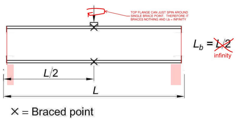
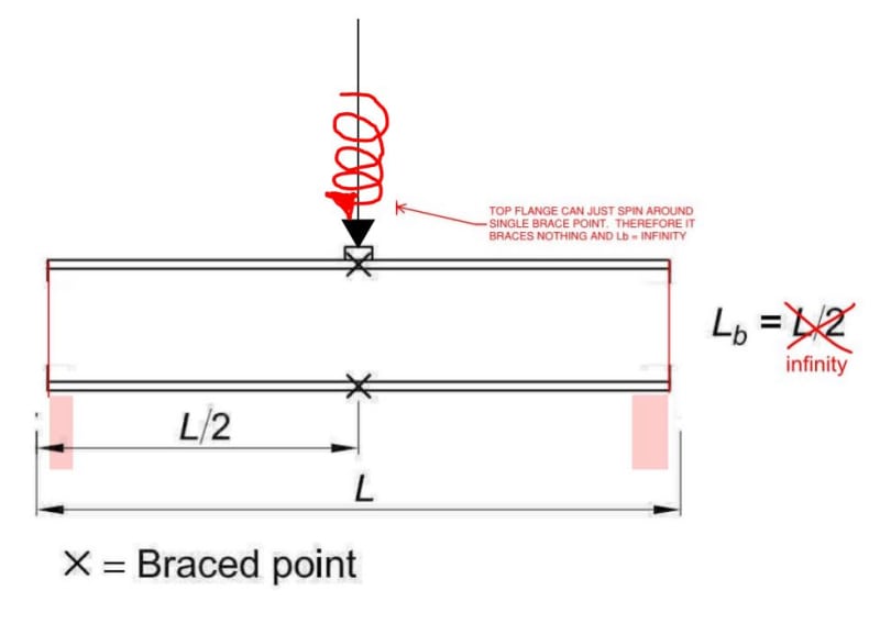
This, because of one of my previous observations, repeated below. Please give that statement additional consideration in conjunction with the sketch that I've provided below. Everything pertains to WSB at the unrestrained bearings rather than at the applied load.

In your sketch you say: "Top Flange can just spin around single brace point. Therefore it braces nothing...."

That isn't the situation I am talking about. Relative to that sketch, I am talking about where the beam is laterally restrained (top and bottom) at (say) the mid-point......and you have a bearing/seat connection at the end (with no restraint). That's where I think sidesway still applies (with lb=l*0.5). And it is a fairly common situation.
 
WARose said:
That isn't the situation I am talking about. Relative to that sketch, I am talking about where the beam is laterally restrained (top and bottom) at (say) the mid-point......and you have a bearing/seat connection at the end (with no restraint). That's where I think sidesway still applies (with lb=l*0.5). And it is a fairly common situation.

You're going to have to baby step me through what you mean here I'm afraid. As far as I can tell, my sketch is exactly the situation that you've described above:

WARose said:
the beam is laterally restrained (top and bottom) at (say) the mid-point.....

Check. Those are the two "x" marks in the sketch.

WARose said:
and you have a bearing/seat connection at the end (with no restraint)

Check. I've shown end connections with bottom flange bearings, no stiffeners, and no discrete bracing to theflanges.

WARose said:
And it is a fairly common situation.

The scenario that I'm envisioning should be extremely rare as it's bad practice and, I believe, explicitly prohibited by many design standards. This leads me to believe that I don't understand the situation that you've described. Can you supply a sketch?


I like to debate structural engineering theory -- a lot. If I challenge you on something, know that I'm doing so because I respect your opinion enough to either change it or adopt it.
 
[blue] (Kootk)[/blue]

You're going to have to baby step me through what you mean here I'm afraid. As far as I can tell, my sketch is exactly the situation that you've described above:

Quote (WARose)
the beam is laterally restrained (top and bottom) at (say) the mid-point.....

Check. Those are the two "x" marks in the sketch.

In the sketch above (i.e. in your post of 8 Apr 18 21:26) you say: "Top Flange can just spin around single brace point. Therefore it braces nothing...."

I'm not talking a single brace point.....I am talking the two "x"'s shown. I'm not sure which situation you are considering here......but in the scenario I am considering, it is impossible for the top flange to "spin around" mid-span because the top and bottom flange are laterally restrained.


WARose said:
but in the scenario I am considering, it is impossible for the top flange to "spin around" mid-span because the top and bottom flange are laterally restrained.

Hmmm... perhaps I have not adequately conveyed to you which axis it is about which the spin would occur. How about now? A brace top and bottom would not restrain this type of movement in the top flange.

WARose said:
I'm not talking a single brace point.....I am talking the two "x"'s shown.

I believe that you are talking about a single brace on the unloaded flange. For the type of motion that I'm considering, the brace to the bottom flange would be irrelevant. What you'd need is two top flange braces to provide restraint.

c01_ihe21j.jpg


I like to debate structural engineering theory -- a lot. If I challenge you on something, know that I'm doing so because I respect your opinion enough to either change it or adopt it.
 
Hmmm... perhaps I have not adequately conveyed to you which axis it is about which the spin would occur. How about now? A brace top and bottom would not restrain this type of movement in the top flange.

Ok....the beam rotating on a axis at mid-span, in and out of the page? Well that isn't possible either based on the scenario I am considering.

For the lateral brace (top and bottom) I am envisioning a full depth (or close to it) beam framing in.....and either the rotational strength of the connection at that point....or multiple braces taking care of that.

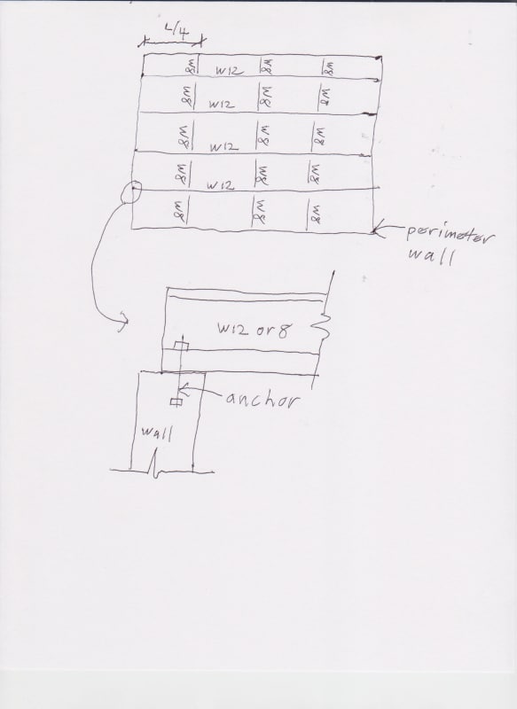
More specifically, I am thinking of a scenario like this:

4.9.18_001_riqcxj.jpg


I've seen that layout about a thousand times at chem/treatment plants (i.e. grating over pits/tanks, occasionally picking up a post load).....and the bearing of the W12 on that wall would seem to me to be susceptible to sidesway (if L/4 got big enough).
 
WARose said:
Ok....the beam rotating on a axis at mid-span, in and out of the page?

Close. Not the beam as a whole, just the unloaded (top) flange. The very flange that one hopes will be providing lateral restraint to a web prone to WSB.

WARose said:
Well that isn't possible either based on the scenario I am considering.

In your scenario, as sketched, your top flange has more than one lateral brace which conflicts with your previous statements about it matching the commentary figure, right? If we've been discussing the commentary figure all this time and what you really meant was this six point bracing scheme with the span equal to four infill framing bays, then surely you can understand why I've been a little slow on the uptake.

While your scenario is better than a single point top flange brace, it's still going to be ineffective as far as the web trying to gain lateral restraint from the flange. That, per my original comment below. Your Lb would be difficult to calculate and would take on some value greater than L/2 (propped cantilever-ish).

KootK said:
2) An unloaded flange that's pretty much worthless as a brace since it's a cantilever with it's fixed end who know's where in the interior of the beam.

I would hope that the connection detail that you sketched is not as common as you've implied. Without stiffeners, it's a WSB nightmare for the reasons just discussed. All you've got stabilizing the unloaded flange from WSB is half a web and no flange. It couldn't even be assessed via the J10.4 equations without modifying those equations substantially, and substantially for the worse.


I like to debate structural engineering theory -- a lot. If I challenge you on something, know that I'm doing so because I respect your opinion enough to either change it or adopt it.
 
[blue](Kootk)[/blue]

If we've been discussing the commentary figure all this time and what you really meant was this six point bracing scheme with the span equal to four infill framing bays, then surely you can understand why I've been a little slow on the uptake.

I could have cut it down to just two and said assume rotational restraint at that point (from the connection).....but rather than starting off on another point.....I felt this cuts to the chase a bit quicker.

[blue](Kootk)[/blue]

While your scenario is better than a single point top flange brace, it's still going to be ineffective as far as the web trying to gain lateral restraint from the flange. That, per my original comment below. Your Lb would be difficult to calculate and would take on some value greater than L/2 (propped cantilever-ish).

Possibly. But I think you could arrive at a number.

[blue](Kootk)[/blue]

I would hope that the connection detail that you sketched is not as common as you've implied. Without stiffeners, it's a WSB nightmare for the reasons just discussed. All you've got stabilizing the unloaded flange from WSB is half a web and no flange. It couldn't even be assessed via the J10.4 equations without modifying those equations substantially, and substantially for the worse.

I've seen it a bunch of times. (Especially in older structures.) Looking at the older calcs.....they'd run with Lb=L/4 (for the LTB check).....and no check on sidesway. (Scary eh? Of course, I don't think sidesway was even part of the code until the 80's.)

Like you said: it presents the same difficulties in sidesway that it does it LTB. I use to work with a guy who compensated by using Lb*2 for LTB, etc. It's been a while since I have had to face it so I cannot remember what I have done. (I'm usually ultra-conservative.)
 
WARose said:
Possibly. But I think you could arrive at a number.

You could arrive at a number. Are we in agreement that:

1) That number -- flange bracing contribution to WSB -- is very likely to be very small.

2) That number cannot be arrived at without DIY tweaking the J10.4 equations or being extremely creative in defining Lb? I can't think of any practical situation where I'd be able to determine Lb by inspection for this condition. And taking it conservatively would mean that one would have to assign a value of more than twice the distance to the nearest brace to Lb.

3) That number is zero for the commentary figure case of a single lateral brace to the top flange? That whole "spin" thing.


I like to debate structural engineering theory -- a lot. If I challenge you on something, know that I'm doing so because I respect your opinion enough to either change it or adopt it.
 
1) That number -- flange bracing contribution to WSB -- is very likely to be very small.

Probably.

2) That number cannot be arrived at without DIY tweaking the J10.4 equations or being extremely creative in defining Lb? I can't think of any practical situation where I'd be able to determine Lb by inspection for this condition. And taking it conservatively would mean that one would have to assign a value of more than twice the distance to the nearest brace to Lb.

Something like that. I'd start by investigating the web distortional stiffness. (As per Appendix 6.)

3) That number is zero for the commentary figure case of a single lateral brace to the top flange? That whole "spin" thing.

With the ends being like the bearing support I drew? Yes, I'd agree with that.
 
Status
Not open for further replies.

Part and Inventory Search

Sponsor