Continue to Site

Eng-Tips is the largest engineering community on the Internet

Intelligent Work Forums for Engineering Professionals

  • Congratulations IDS on being selected by the Eng-Tips community for having the most helpful posts in the forums last week. Way to Go!

Steel Beam Bearing - ASIC J10.4 Web Sidesway Buckling 5

Status
Not open for further replies.

RFreund

Structural
Aug 14, 2010
1,881
I am trying to clarify J10.4 in AISC - Web Sidesway Buckling. I might be a little picky here, but I want to make sure I understand this correctly.
AISC gives two different equations depending on whether or not the compression flange is restrained against rotation. Here is my confusion:

J10.4 -
"This section applies only to compressive single-concentrated forces applied to mem-
bers where relative lateral movement between the loaded compression flange and the
tension flange is not restrained at the point of application of the concentrated force."

J10.4a
"If the compression flange is restrained against rotation"
J10.4b
"If the compression flange is not restrained against rotation"

"When the required strength of the web exceeds the available strength, local
lateral bracing shall be provided at both flanges at the point of application of the
concentrated forces."

Comm J10.4
"The web sidesway buckling provisions (Equations J10-6 and J10-7) apply only to
compressive forces in bearing connections and do not apply to moment connections.
The web sidesway buckling provisions were developed after observing several unex-
pected failures in tested beams (Summers and Yura, 1982; Elgaaly, 1983). In those
tests, the compression flanges were braced at the concentrated load, the web was sub-
jected to compression from a concentrated load applied to the flange, and the tension
flange buckled (see Figure C-J10.2)."

Comm J10.4a
"For flanges restrained against rotation (such as when connected to a slab), when.."

Comm J10.4b
"For flanges not restrained against rotation, when"

Alright, so my questions:
[ol 1]
[li]In my first snippet AISC states this limit states only applies to beams where relative lateral movement between flanges is not restrained. However, Figure C-J10.2 (or J10.3 depending on edition) defines the unbraced lengths used in the web sidesway buckling equations. The last figure shows the top and bottom flange braced at the location of the concentrated load and defines the unbraced flange length as L/2. Shouldn't the limit state not apply?[/li]
[li]AISC states for flanges "restrained against rotation", do they mean - the local compression flange is restrained against rotation or the entire section is restrained against rotation? Or do they mean that the compression flange is restrained against lateral translation? In figure CJ10.1 they show the compression flange as being braced against lateral translation. Also in the commentary they state "(such as when connected to a slab)".[/li]
[li]Would this apply to the end of a uniformly loaded beam? I want to say no, because it states the "loaded compression flange". In the case of the end of a beam, you would have a "loaded tension flange".[/li]
[/ol]

Thanks!

EIT
 
Replies continue below

Recommended for you

WARose said:
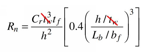
Actually it does (at least in the 13th edition). Equations J10-6 (i.e. compression flange restrained against rotation) and J10-7 (i.e. compression flange not restrained against rotation) both have web thickness as a variable.

Actually it doesn't. Gotta bust out a little 8th grade algebra to drill down to the truth of it.

It drives me a little nuts the way that AISC does this sometimes. They do a bunch of unnecessary algebraic manipulation to make the equations look "consistent" and, in the process, confuse the heck out everybody with regard to the true nature of the expressions. Jury rigging things to include variables that aren't even legit parameters... Timoshenko would not be impressed.

c01_flp6cr.jpg


I like to debate structural engineering theory -- a lot. If I challenge you on something, know that I'm doing so because I respect your opinion enough to either change it or adopt it.
 
WARose said:
To my mind, it's just about absolutely impossible for the web to buckle (in sidesway) with a large number of stiffeners present.

Let's try this another way. A concentrated flange load will produce a rollover tendency (buckling) in a wide flange beam with imperfection. Hopefully we're in agreement there. Are you able to articulate why you think that stiffeners would aid in resisting that tendency in the absence of loaded flange rotational restraint? What is the mechanism of resistance in that scenario? I know that you don't think it's torsional capability as you've mentioned the results of your FEM studies on several occasions in reference to the biannual "do stiffeners resist torsion" threads.


I like to debate structural engineering theory -- a lot. If I challenge you on something, know that I'm doing so because I respect your opinion enough to either change it or adopt it.
 
Actually it doesn't. Gotta bust out a little 8th grade algebra to drill down to the truth of it.

It drives me a little nuts the way that AISC does this sometimes. They do a bunch of unnecessary algebraic manipulation to make the equations look "consistent" and, in the process, confuse the heck out everybody with regard to the true nature of the expressions.

Oh those tricky AISC engineers!

Let's try this another way. A concentrated flange load will produce a rollover tendency (buckling) in a wide flange beam with imperfection. Hopefully we're in agreement there. Are you able to articulate why you think that stiffeners would aid in resisting that tendency in the absence of loaded flange rotational restraint? What is the mechanism of resistance in that scenario? I know that you don't think it's torsional capability as you've mentioned the results of your FEM studies on several occasions in reference to the biannual "do stiffeners resist torsion" threads.

I think at that point you would be engaging the whole of the beam (if it had the proper rotational restraint at the ends). And yes, a single (or even several) stiffeners are really not going to alter things as far as the beam's rotational properties go. But adding one every few inches (say the depth of the beam divided by two)? That's got to change things.

If I have time, I might take a look at it with a model today. (Thanks for this discussion by the way.)
 
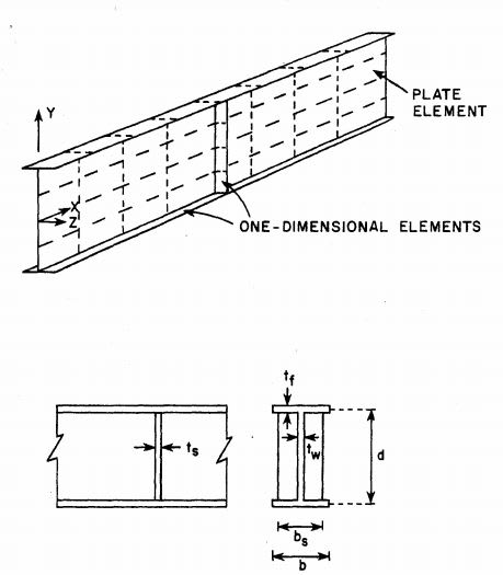
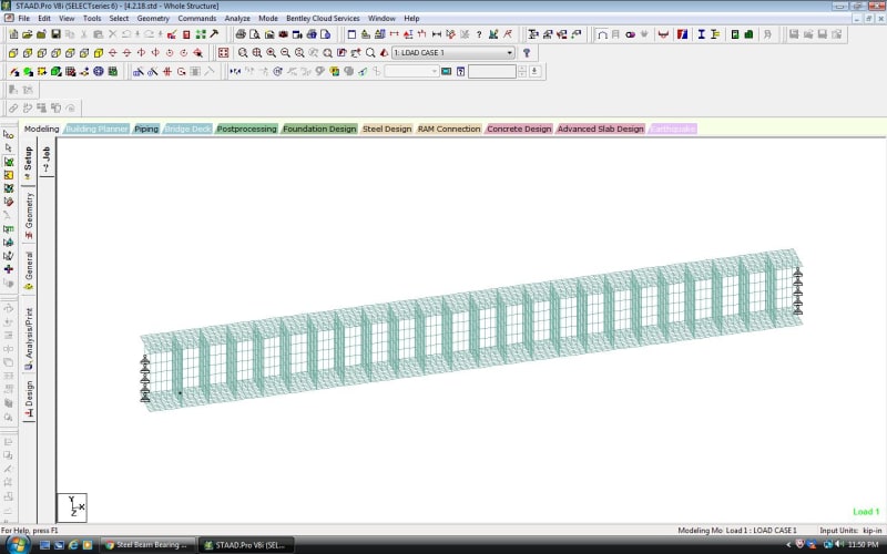
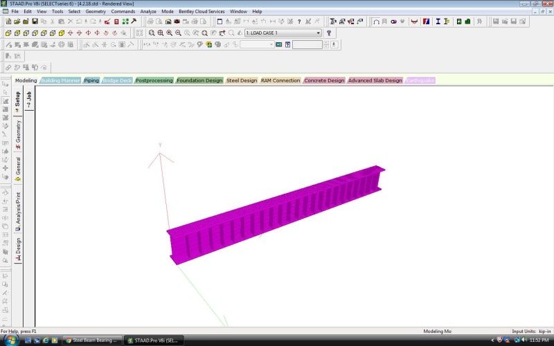
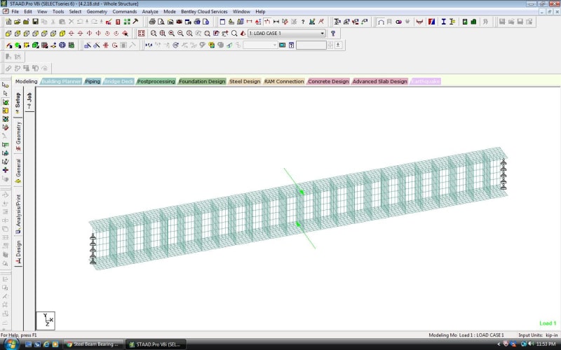
Ok, I ran a beam with and without a ton of stiffeners. (Via STAAD using all plate elements.) I modeled a W12x30 (with a 10' span) and put a 120 in-k torque at mid-span. (By putting in point loads as lateral loads applied to the flange edges.) In the first model, I had a bunch of (full depth) stiffeners: 0.5" thick, spaced 5" o.c., and fully fixed to the flange and web. No corner "clips", and it's 23 pairs of stiffeners in all. The only restraint was a "pin" support starting 2" below each flange and going along the full length of the web at each end. (About 5" away from the first stiffener on each end.) The results I give are for the center-line of the web at mid-span.

The results for the applied torque:

W12 without stiffeners: 0.223 rad rotation

W12 with stiffeners: 0.138 rad rotation

[Theoretical rotation (without stiffeners via a spreadsheet I have): 0.153 rad]

Just to make sure I wasn't getting some sort of distortional affect in the model without stiffeners.....I ran a third model with a single stiffener at the point the torque was applied. It did not significantly alter the rotation.

Extrapolating the added rotational stiffness from the added stiffeners (just comparing STAAD models) we get 74 in-k/0.085 rad. And that equals 870.58 kip-inch/rad.

How does that compare to required torsional/rotational stiffness for beams as per Appendix 6? That covers the required rotational stiffness for some light to medium loaded beams in such cases ......not quite there for a heavily loaded beam.

But this demonstrates rotational stiffness can be added by lots of stiffeners.....that would likely preclude sidesway failure (where the compression flange is not restrained against rotation)......but a number that would be impractical. (Which explains its omission from the code.)

Will continue to collate results (where time permits) and advise anything I find of interest.
 
Neat! Thanks for the extracurricular hustle WARose.

WARose said:
But this demonstrates rotational stiffness can be added by lots of stiffeners

For me, this conclusion was never really in doubt for systems of such extreme proportions. With fixed, 1/2" thick x 12" tall stiffeners at 5" o/c, I would expect the stiffeners to behave somewhat like vierendeel trusses acting to restrain the warping component of torsional deformation. If you are able spare the time for another kick at the cat, how about:

- W18x40
- L = 24'
- 3/8" stiffeners @ 24" o/c

I would consider that arrangement to be nearer the border between practical and excessive. I'd do it myself but, alas, I don't have access to expedient software for plate FEM these days.

WARose said:
....that would likely preclude sidesway failure (where the compression flange is not restrained against rotation)......but a number that would be impractical. (Which explains its omission from the code.)

As I understand it, your logic here is this, each point following from it's predecessor:

1) Wildly impractical stiffener arrangements will torsionally stiffen wide flange beams.

2) Torsionally stiffened beams effectively brace the unloaded flanges laterally.

3) Braced, unloaded flanges effectively brace webs against side sway buckling.

4) AISC considers stiffeners to be valid torsional bracing but chose not to codify that design strategy for web sway buckling because they felt that the extremely tight stiffener spacings required would render the strategy impractical.

5) AISC considers web sway buckling to apply between concentrated loads because they do consider stiffeners located between concentrated to be effective for web sway buckling even though they make no mention of that strategy owing to it's impracticality.

That all seems like a pretty tenuous logical leap to me. In my opinion, it's vastly more likely that AISC didn't provide an "in the field" stiffener alternative because they consider the web sway instability to be completely resolved with the addition of a single pair of stiffeners located at the concentrated load (given load flange rotational restraint, of course). Any additional stiffeners would be redundant.

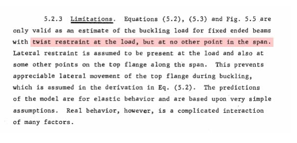
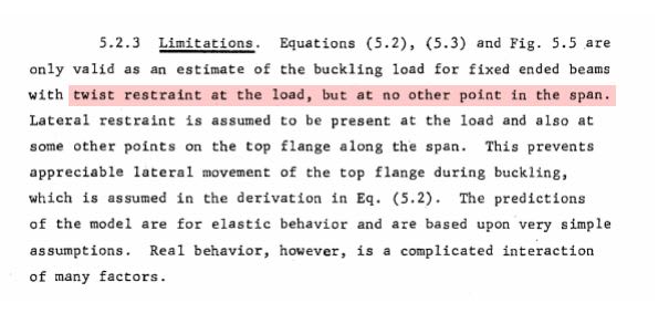
I believe this to be the Yura document that served as the basis for AISC's current web sway buckling provisions. The rabbit hole goes even deeper than I thought with considerations of web/flange junction platicity, moment gradient etc. Some sexy Plexiglas physical modelling too.... Anyhow, I note the following which I feel lend some credence to my thinking here:

1) None of the testing performed involved stiffeners other than those included at the concentrated load and at the support.

2) None of the FEM modelling performed involved any stiffeners other than those included at the concentrated load and at the support.

3) The "Limitations" section describes the results as being only applicable to beams rotationally restrained at the point of load application and only the point of load application.

c01_j8eipg.jpg


c02_taehyj.jpg


I like to debate structural engineering theory -- a lot. If I challenge you on something, know that I'm doing so because I respect your opinion enough to either change it or adopt it.
 
If you are able spare the time for another kick at the cat, how about:

- W18x40
- L = 24'
- 3/8" stiffeners @ 24" o/c

I would consider that arrangement to be nearer the border between practical and excessive. I'd do it myself but, alas, I don't have access to expedient software for plate FEM these days.

Will do. (Possibly either tomorrow or Thursday.)

As I understand it, your logic here is this, each point following from it's predecessor:

1) Wildly impractical stiffener arrangements will torsionally stiffen wide flange beams.

2) Torsionally stiffened beams effectively brace the unloaded flanges laterally.

3) Braced, unloaded flanges effectively brace webs against side sway buckling.

4) AISC considers stiffeners to be valid torsional bracing but chose not to codify that design strategy for web sway buckling because they felt that the extremely tight stiffener spacings required would render the strategy impractical.

5) AISC considers web sway buckling to apply between concentrated loads because they do consider stiffeners located between concentrated to be effective for web sway buckling even though they make no mention of that strategy owing to it's impracticality.

That all seems like a pretty tenuous logical leap to me.

I don't know about #4 or 5. Let me be clear: [red]I[/red] think that is what happens.....but AISC probably doesn't know (or care) because it may be they they just didn't feel it was worth researching. (Given the practicality issues that I stated.)

As far as #2 goes: I think the numbers back it up pretty strongly. To go back to the W12x30.....I give the added rotational stiffness as 870.58 kip-inch/rad (from the 23 pairs of stiffeners). Breaking that into a laterally bracing couple, we are talking about 8 kips/in of bracing stiffness at each flange. Treating the web like a column (referencing your pic in your post of 1 Apr 18 20:11), and Looking at Appendix 6 (ASD)....that's well within the required bracing stiffness for such a "column" (after spreading out the load a bit) once that W12 gets up to the point where sidesway starts coming into play. (I.e. around 15' of unbraced length and a load of around 54 kips.)

I believe this to be the Yura document that served as the basis for AISC's current web sway buckling provisions. The rabbit hole goes even deeper than I thought with considerations of web/flange junction platicity, moment gradient etc. Some sexy Plexiglas physical modelling too.... Anyhow, I note the following which I feel lend some credence to my thinking here:

1) None of the testing performed involved stiffeners other than those included at the concentrated load and at the support.

2) None of the FEM modelling performed involved any stiffeners other than those included at the concentrated load and at the support.

3) The "Limitations" section describes the results as being only applicable to beams rotationally restrained at the point of load application and only the point of load application.

Thanks for the paper.....will read. I don't follow (though) why you feel it lends credence to your theory. It could (also) just as easily be said that such testing wasn't done for the practicality reasons I gave. (Or cost. Putting that many stiffeners in would get expensive for university research. Especially when you start thinking about the almost limitless number of permutations of stiffener thickness, spacing, etc.)


WARose said:
Will do. (Possibly either tomorrow or Thursday.)

If you do get around to it, let's go with w16x26. I'm finding that the bulk of the work out there is Yura's and the overwhelming bulk of what he tested and analyzed was W16x26. If you investigate that beam size, we might be able to make some meaningful comparisons to existing testing etc.

WARose said:
As far as #2 goes: I think the numbers back it up pretty strongly.

Could you post your calc and some screen shots of your FEM model? As it stands, I don't really have any convenient means of critiquing your conclusions.

WARose said:
It could (also) just as easily be said that such testing wasn't done for the practicality reasons I gave.

And it could just as easily be said that the unloaded flanges are restrained by Martian tractor beams but that the researchers decided it would be impractical to try to track down some Martians. Levity aside, it's similar logic. I've claimed that the AISC provisions don't consider rotational restraint between loads and I've backed that up by showing that the research underpinning the provisions also doesn't consider rotational restraint between loads. You seem to be claiming that the writers of the specification must have considered and rejected stiffeners between load points, even though that's not mentioned anywhere, based on your personal beliefs and your own FEM model. Surely you'll agree that our two claims have not been substantiated in equal measure?

WARose said:
I don't follow (though) why you feel it lends credence to your theory

My theory is that the AISC checks for web sway buckling don't apply between concentrated loads and, as a result, neither additional rotational restraint nor additional stiffeners are required between concentrated loads. Does the highlighted sentence below not suggest that similar reasoning was used in the development of the provisions? It was taken from the research (Yura) that underpins our current provisions for web sway buckling.

c01_alq0xg.jpg


I like to debate structural engineering theory -- a lot. If I challenge you on something, know that I'm doing so because I respect your opinion enough to either change it or adopt it.
 
If you do get around to it, let's go with w16x26.

What do you want in terms of length (of the beam), stiffener spacing, and stiffener size?

Could you post your calc and some screen shots of your FEM model? As it stands, I don't really have any convenient means of critiquing your conclusions.

The hand calculations are on scratch paper. (Not real formal.) But you can confirm some of this with the numbers I gave you. (I.e. rotational stiffness, etc.)

As far as screen shots......see below.

4.2a.18_fx0zyj.jpg


4.2c.18_eteoir.jpg


4.2d.18_yec0al.jpg


You seem to be claiming that the writers of the specification must have considered and rejected stiffeners between load points, even though that's not mentioned anywhere, based on your personal beliefs and your own FEM model. Surely you'll agree that our two claims have not been substantiated in equal measure?

I think it's speculation on both our parts. And it's pointless to keep arguing about speculation.

My theory is that the AISC checks for web sway buckling don't apply between concentrated loads and, as a result, neither additional rotational restraint nor additional stiffeners are required between concentrated loads. Does the highlighted sentence below not suggest that similar reasoning was used in the development of the provisions? It was taken from the research (Yura) that underpins our current provisions for web sway buckling.

What it suggests is what his criteria was. He also says this: "Real behavior, however, is a complication interaction of many factors."

I agree. Note the AISC article I cited elsewhere in this thread that said the code equations on this are very conservative (i.e. not accurate).

And again: I am not saying AISC is wrong. Just that their statement in J10.4.b (omitting stiffeners) is (probably) for practical purposes.
 
WARose said:
What do you want in terms of length (of the beam), stiffener spacing, and stiffener size?

What do you think is a reasonable span:depth for a member transferring a good sized concentrated load? Eighteen maybe so about 24'?

WARose said:
The hand calculations are on scratch paper. (Not real formal.) But you can confirm some of this with the numbers I gave you. (I.e. rotational stiffness, etc.)

I'll happily take the hand calcs on scratch paper. Like you, I'm a busy guy. If I have something in hand to review I'll probably make the time. If I'm trying to recreate it on my own from scratch, I almost certainly never will.

Rose said:
The only restraint was a "pin" support starting 2" below each flange and going along the full length of the web at each end. (About 5" away from the first stiffener on each end.)

Now that I've seen your model screen captures, I understand this. I thought that you'd meant a continuous lateral support along the length of the beam 2" down from the loaded flange. I think that the model should have continuous lateral support but located at the loaded flange. I think that would move the needle some from being a pure torsion situation to something more like the bottom flange acting as a lateral girt which is consistent with the models used in the literature, particularly for deeper members.

WARose said:
I think it's speculation on both our parts. And it's pointless to keep arguing about speculation.

I disagree on both counts. My claims match what the specification says if you take it literally, word for word, save the one incongruous commentary figure which is in debate. My claims also match what is shown in the Yura research that led to the code provisions. Your claims, while having logical merit as demonstrated by your FEM work, do not show up explicitly in either the specification or the research.

So the point that I've been trying to gently make is this: while we both may be making inferences, mine would seem to have a much stronger basis of support. But then, of course, that is my inevitably biased opinion. Let's not pussyfoot around the reality of things here. We're having a gentlemanly/womanly, technical debate. And that means that I'm trying to persuade you that my reasoning is superior to yours. While most of that process entails me trotting out my best ideas, some also entails me poking holes in your arguments where I feel that there is weakness. This is that.

WARose said:
What it suggests is what his criteria was.

It suggests what his criterion were which then got incorporated into what our specification requirements now are. That seems like a pretty big deal to me.

WARose said:
And again: I am not saying AISC is wrong. Just that their statement in J10.4.b (omitting stiffeners) is (probably) for practical purposes.

I see this as fundamental though. When I look at the development of the design equations, it seems obvious to me that intermediate stiffeners would not be an option because they simply don't have a place in the behavioral model used to generate the design equations. And you clearly see this very differently, as a matter of practicality rather than as a fundamental feature of the behavioral model.

I get that your FEM model demonstrates some stiffener efficacy this regard. That, however, is not my primary focus here. I'm less interested in what may or may not work and more interested in what AISC's intent is.

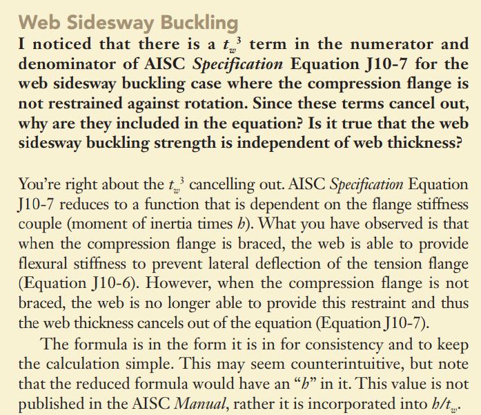
Check out the snippet below from a Steel Interchange article of old. It seems that others have been curious about the tw cancellation too. And the response seems to be in line with my thinking: webs are considered to restrain the unloaded flange by cantilevering down to the unloaded flange from a rotationally fixed top flange. Therefore, they are useless when the top flange is not rotationally restrained. We kind of glossed over the argument that I was trying to make with that in our side debate as to whether or not tw was a real parameter. The argument that I'd intended to make was this:

1) Stiffeners address side sway buckling primarily by adding stiffness and strength to the web and thereby restraining its distortion.

2) For the case where there is no loaded flange rotational restraint, the design equation does not give any account to the stiffness or strength of the beam web, suggesting that it is not a significant behavioral factor.

3) If the stiffness and strength of the beam web are irrelevant for the unrestrained case, then surely increases to the stiffness and strength of the beam web by way of intermediate stiffeners are also irrelevant.

4) If intermediate stiffeners are of no design relevance for the unrestrained case, I take that as indicative of side sway buckling not being an issue between concentrated loads.

I'm making a few logical leaps of my own here but I think that the argument has merit.

c01_dxhw0n.jpg


I like to debate structural engineering theory -- a lot. If I challenge you on something, know that I'm doing so because I respect your opinion enough to either change it or adopt it.
 
What do you think is a reasonable span:depth for a member transferring a good sized concentrated load? Eighteen maybe so about 24'?

To me, the question is about affecting the rotational properties of the member. To my mind that's coming with a stiffener spacing equal to the depth of the beam or the depth divided by two. (For the W12 I modeled above I used a little less than d/2.) I've modeled (as you know) beams with stiffeners before.....and my observation is: it takes lots for anything to be changed as far as rotational stiffness goes.

I'll happily take the hand calcs on scratch paper. Like you, I'm a busy guy. If I have something in hand to review I'll probably make the time. If I'm trying to recreate it on my own from scratch, I almost certainly never will.

I'll see what I can come up with (maybe the next go around with this W16). But the rotational stiffness calc (for example) is pretty straight forward. (I.e. applied torque given, rotation given, etc.)

Now that I've seen your model screen captures, I understand this. I thought that you'd meant a continuous lateral support along the length of the beam 2" down from the loaded flange. I think that the model should have continuous lateral support but located at the loaded flange. I think that would move the needle some from being a pure torsion situation to something more like the bottom flange acting as a lateral girt which is consistent with the models used in the literature, particularly for deeper members.

I supported it that way because I didn't want anything resembling a rotationally supported flange. The test here is: can the member (with a ridiculous number of stiffeners) essentially brace itself (for a lack of a better way to put it) with it's new rotational properties....without flange rotation support as per Section J10.4.(b).

So the point that I've been trying to gently make is this: while we both may be making inferences, mine would seem to have a much stronger basis of support.

That's your opinion.....but until you show me a test with tightly spaced stiffeners that involved sidesway.......it's just that (i.e. your opinion).

Check out the snippet below from a Steel Interchange article of old. It seems that others have been curious about the tw cancellation too. And the response seems to be in line with my thinking: webs are considered to restrain the unloaded flange by cantilevering down to the unloaded flange from a rotationally fixed top flange. Therefore, they are useless when the top flange is not rotationally restrained.

I've seen that. But (again): it's apples and oranges. That is regarding a normal case of a handful of stiffeners. That is not what I am considering.


WARose said:
To my mind that's coming with a stiffener spacing equal to the depth of the beam or the depth divided by two.

Yeah, I would have gone depth or depth multiplied by two. Tomayto, tomaughto.

WARose said:
I've modeled (as you know) beams with stiffeners before.....and my observation is: it takes lots for anything to be changed as far as rotational stiffness goes

I remember as it's always caught my eye. If my theory about the stiffeners behaving like Vierendeel trusses to restrain warping is correct, then this effect should diminish with beam depth in proportion to the cube of beam depth. You know, ish. So I'd expect it to take about eight times as many stiffeners to get the job done on a W24 as it would with a W12. By then you've got a solid steel box. I imagine it's somewhat less than a cubic relation as the beams of the vierendeel truss are getting shorter as web spacing decreases so each little moment frame is getting that much stiffer on the beam side.

WARoss said:
But the rotational stiffness calc (for example) is pretty straight forward. (I.e. applied torque given, rotation given, etc.)

Straight forward for you when you're following your own self invented calc. If I'd attempted this last night, I would have assumed lateral restraint at the top flange and been way off.

WARose said:
I supported it that way because I didn't want anything resembling a rotationally supported flange. The test here is: can the member (with a ridiculous number of stiffeners) essentially brace itself (for a lack of a better way to put it) with it's new rotational properties....without flange rotation support as per Section J10.4.(b).

Here, I think, our interests diverge. I'm not actually that interested in the zillion stiffener business for it's own sake. I'm only interested in it as a device for determining whether or not AISC intends for us to address web sway buckling at locations away from concentrated loads. As such, the FEM model that I'll never get around to creating would have top flange lateral restraint as it does in J10.4 and as it often would in the wild.

WARose said:
That's your opinion.....but until you show me a test with tightly spaced stiffeners that involved sidesway.......it's just that (i.e. your opinion).

That's the thing, it's not just my opinion. It's a) my opinion b) what is described in the AISC spec if read literally and c) what is manifest in the research that informed the AISC spec.

WARose said:
But (again): it's apples and oranges. That is regarding a normal case of a handful of stiffeners. That is not what I am considering.

Again, our interests seem to have diverged. And that's fine. You're hot and bothered by the zillion stiffener business and I'm wanting to know the rules of the land as they've been set forth by AISC. That an ungodly number of stiffeners would eventually affect torsional response is no surprise to me, even if the exact details of it are of great interest. Really, my stance on the stiffeners only requires a slight modification to one of my previous comments:

KootK said:
They're not saying that you should add more stiffeners when there is no rotational restraint at the loaded flange. Rather, they're saying that, sans rotational restraint to the loaded flange, stiffeners are utterly useless at any location from the perspective of the behavioral model assumed in the AISC spec and a zillion of them wouldn't make a lick of difference from the perspective of the behavioral model assumed in the AISC spec.

Clearly, as you've demonstrated, a zillion stiffeners would make a difference in the real world. Literary license and hyperbole...


I like to debate structural engineering theory -- a lot. If I challenge you on something, know that I'm doing so because I respect your opinion enough to either change it or adopt it.
 
Yeah, I would have gone depth or depth multiplied by two. Tomayto, tomaughto.

Ok so do you still want me to run it? The criteria is:

-W16x26
-L=24'
-Stiffener thickness= 3/8"
-Stiffener spacing= 8"

I remember as it's always caught my eye. If my theory about the stiffeners behaving like Vierendeel trusses to restrain warping is correct, then this effect should diminish with beam depth in proportion to the cube of beam depth. You know, ish. So I'd expect it to take about eight times as many stiffeners to get the job done on a W24 as it would with a W12. By then you've got a solid steel box. I imagine it's somewhat less than a cubic relation as the beams of the vierendeel truss are getting shorter as web spacing decreases so each little moment frame is getting that much stiffer on the beam side.

Probably some truth to that. If you look at Appendix 6, the equation that takes into account the web distortional stiffness (for torsional bracing) has a portion that is devoted to the added effect stiffeners provide. (Eq. A-6-12) Multiplying the terms out.....it would seem you'd have to proportionally increase the stiffener thickness as the depth increases to have the same rotational stiffness.


Straight forward for you when you're following your own self invented calc.

True. I'll write it out on the next go around (if you want me to run that W16).

Here, I think, our interests diverge. I'm not actually that interested in the zillion stiffener business for it's own sake. I'm only interested in it as a device for determining whether or not AISC intends for us to address web sway buckling at locations away from concentrated loads. As such, the FEM model that I'll never get around to creating would have top flange lateral restraint as it does in J10.4 and as it often would in the wild.

AISC's provision are meant for us to [red]avoid[/red] having to "address web sway buckling at locations away from concentrated loads". The unbraced length of the beam is a factor in both Eq. J10-6 & J10-7. If you exceed that (and the capacity)....you likely will have problems at other locations (as well as the usual suspects). In the commentary for J10 it says: "(Equations J10-6 and J10-7) apply only to compressive forces in bearing connections". I believe there they are referring to a seated connection, bearing on a wall, etc. But you look at Fig. C-J10.1, they are showing it from a point load somewhere along the span. That's what leads me to watch out for this anywhere. (Best policy is to set a braced length to preclude it completely.)

That's the thing, it's not just my opinion. It's a) my opinion b) what is described in the AISC spec if read literally and c) what is manifest in the research that informed the AISC spec.

And what testing is that backed up by? Nothing. So we have no testing and a code whose language is confusing.

And since when do the codes address every situation and are 100% accurate? Where in AISC does it give guidance for transferring a torque in connections? When Appendix D (in ACI 318) first came out, what did it say about anchor reinforcement? What does Appendix D currently say about high cycle loading? (The answer to the above questions (in order) are: Nothing. Virtually nothing. Zilch (other than: we don't touch it).)


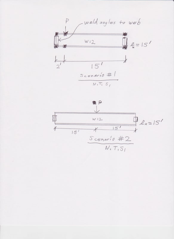
To illustrate my point (looking back over my posts, I'm not sure if I have been clear enough as to my many suspicions with this provision), please consider the following scenarios (building on Figure C-J10.2):

4.4.18_001_pmmdjs.jpg


In both cases, I consider the compression flange restrained against rotation (and lateral translation).

Ok, considering Scenario #1.....if P was (say) equal to twice the sidesway capacity of the beam (and lu at that point is 15'), you'd put in a stiffener or doubler plate (as per J.10.4.(a)).

Obviously the same deal with Scenario #2.....but wait....what about the ends? Why would you have to use a stiffener in Scenario #1 but not the ends in Scenario #2? The situation is almost [red]identical.[/red] In fact, if it was close enough, you'd wind up having a stiffener just about [red]on[/red] the clip angles. (As per the code. And the allowable sidesway makes no provision for the load's location on the beam, just the largest unbraced length.) If the load was high enough (in the middle) and the unbraced length was long enough....any stress distribution probably would bail you out either.

You could make the case for the end clip angles acting as a doubler plate (what about a knife plate connection?) or rotational stiffness provided by the connection (moot point since the largest lu controls). But hopefully this illustrates why I've always been wary of trying to address this by anything other than cutting down on unbraced length......and also why I think it is probably applicable to more situations than just bearing or point load.
 
WARose said:
Ok so do you still want me to run it?

I do but:

1) I'd want you to run it my way. 1D stiffeners; lateral restraint at the top; lateral flange point load at the bottom center.

2) My way may well already have been FEM'd in Yura's stuff. I've got a lot left to digest.

So I probably shouldn't ask you to waste your valuable time just yet.

WARose said:
AISC's provision are meant for us to avoid having to "address web sway buckling at locations away from concentrated loads".

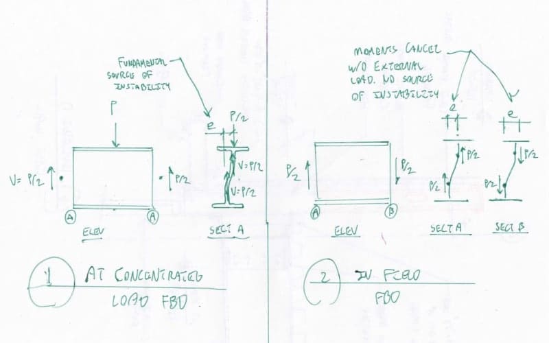
Says you. I say the demand doesn't exist. In fact, I'd very much like it if someone who disagrees with me would respond to my FBD challenge above. If it's real, it should be FBD-able.

WARose said:
In the commentary for J10 it says: "(Equations J10-6 and J10-7) apply only to compressive forces in bearing connections". I believe there they are referring to a seated connection, bearing on a wall, etc. But you look at Fig. C-J10.1, they are showing it from a point load somewhere along the span. That's what leads me to watch out for this anywhere. (Best policy is to set a braced length to preclude it completely.)

Really? Gawd no. They're talking about columns getting transferred and stuff like that. Why would they target end bearing connections and then exclusively test midspan loading? Additionally, as I pointed out in a previous comment, the unloaded flange that's doing the bracing is almost infinitely stiff at the beam ends so it's a non-issue either way.

WARose said:
And what testing is that backed up by? Nothing.

My claim wasn't that tightly spaced stiffeners had no effect. My claim was that behavior model underlying the code equations assigns zero value to stiffeners when the loaded flange is unrestrained. And that assertion requires no testing. One merely needs to look at the code and the research to see that this is true. If you disagree with that stance, take it up with Yura and AISC. I have no horse in that race.

I find it highly unlikely that there is or ever will be testing done on the zillion stiffener solution. Precious research grant money usually gets allocated to exploring things that someone might actually want to do in practice. This 'aint that. I'd expect any investigation into this to responsibly end with FEM exploration similar to what you've already done.

WARose said:
And since when do the codes address every situation and are 100% accurate?

I never implied that AISC is infallible. In fact, for reasons unique to my own experience, I'm pretty skeptical of their Steel Solutions Center. What I am saying is simply that, of the two statements made below, the first carries more weight in my opinon:

1) KootK claim. Mirroed in AISC spec and research informing AISC spec.

2) WARose claim. Mirrored by single data point, personal FEM testing and no AISC mentions.

I'm not saying that your claim is worthless. It's just worth less than mine given the various forms of evidence that we've each provided for our positions so far. And, obviously, I'm far from impartial.

How long does it typically take AISC to respond to questions anyhow? I've not tapped that resource in the past. Maybe we'll luck out and get a response from Teddy, Joseph or the ghost of Omer.


I like to debate structural engineering theory -- a lot. If I challenge you on something, know that I'm doing so because I respect your opinion enough to either change it or adopt it.
 
So I probably shouldn't ask you to waste your valuable time just yet.

Ok.

Says you. I say the demand doesn't exist. In fact, I'd very much like it if someone who disagrees with me would respond to my FBD challenge above. If it's real, it should be FBD-able

See the Scenario #1 & 2 I post above. The logic of this provision doesn't make much sense.

Really? Gawd no. They're talking about columns getting transferred and stuff like that. Why would they target end bearing connections and then exclusively test midspan loading? Additionally, as I pointed out in a previous comment, the unloaded flange that's doing the bracing is almost infinitely stiff at the beam ends so it's a non-issue either way.

They say point blank: bearing. I don't see how that could be interpreted any other way. It's the same thing....but inverted.

I'm not being a wiseguy here but: is this smart steel? Does it know load is being transferred by a column bearing vs. a short seat?


I find it highly unlikely that there is or ever will be testing done on the zillion stiffener solution. Precious research grant money usually gets allocated to exploring things that someone might actually want to do in practice. This 'aint that. I'd expect any investigation into this to responsibly end with FEM exploration similar to what you've already done.

Fair enough. I said the same thing.

I never implied that AISC is infallible. In fact, for reasons unique to my own experience, I'm pretty skeptical of their Steel Solutions Center. What I am saying is simply that, of the two statements made below, the first carries more weight in my opinon:

1) KootK claim. Mirroed in AISC spec and research informing AISC spec.

2) WARose claim. Mirrored by single data point, personal FEM testing and no AISC mentions.

And in [red]every[/red] one of those tests I have seen.....not one had a angle connection that wasn't fortified by a stiffener or something like that. Even the Daniels & Fisher test (referenced in Yura's paper which I have downloaded) have end bearings and stiffeners at each end.

I'm not saying that your claim is worthless. It's just worth less than mine given the various forms of evidence that we've each provided for our positions so far. And, obviously, I'm far from impartial.

And all I am saying is: people should be mighty careful with this. Like my first boss use to say: "When in doubt....make it stout."

How long does it typically take AISC to respond to questions anyhow? I've not tapped that resource in the past. Maybe we'll luck out and get a response from Teddy, Joseph or the ghost of Omer.

Don't know that one. Got a auto reply that said something about expect a delay due to some server problems. You yourself said you don't 100% trust them.......not sure I do either. But I'd be curious to hear if any debate has busted out on this at AISC over the years.
 
WARose said:
Ok, considering Scenario #1.....if P was (say) equal to twice the sidesway capacity of the beam (and lu at that point is 15'), you'd put in a stiffener or doubler plate (as per J.10.4.(a)).

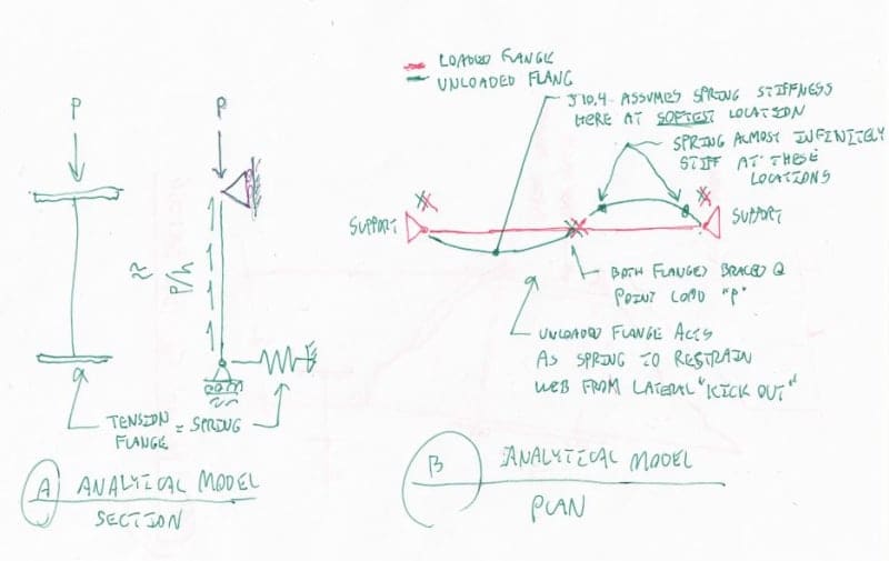
I'd put a stiffener in without even checking J10.4 as I simply think that it's good practice to do so. Were I basing my decision solely on J10.4, however, I would consider myself to have choice in the matter. Were I feeling lazy, I would just follow J10.4 and add stiffeners. Were I feeling motivated to the omit the stiffeners, I would refine the calculation to reflect the fact that the bottom flange performing the bracing function is almost infinitely stiff laterally at the end of the beam. Thus the bracing stiffness is vastly higher than considered in J10.4 which assumes that the point load occurs at mid-span. See the comment above where I introduced the first sketch below.

WARose said:
Why would you have to use a stiffener in Scenario #1 but not the ends in Scenario #2? The situation is almost identical.

I disagree, the two cases are polar opposites from a stability standpoint. Put simply, scenario one has stability demand near the end where scenario two has none. You can see this easily by doing the FBD exercise that I did previously where I introduced the second sketch below.

Here's another way to think of it. Any genuine instability in the system will cause the system to shed potential energy and the applied load to move closer to mother earth. If you took scenario two and somehow induced some web buckling locally, near the end, the load at the center would not move closer to the earth appreciably. If you conducted that same experiment for scenario one, with the load at the buckled locations, the load would definitely move closer to the earth. And, at the end of the day, that's all that you really need to know. The rest is just mathematics that I'm probably no longer fit to undertake if, indeed, I ever was.

WARose said:
As per the code. And the allowable sidesway makes no provision for the load's location on the beam, just the largest unbraced length.

This is not correct. The code provisions assume a stability demand at the center of the beam where the unloaded flange, which does the "bracing", is at it's least stiff. Review any of the papers that we've been bandying about and you'll see the PL^3/48EI business pop up from time to time. From a stability perspective, a load anywhere else on the span is better. As I mentioned previously, multiple loads do give me pause.

c01_b3ey7u.jpg

c02_soekfq.jpg


I like to debate structural engineering theory -- a lot. If I challenge you on something, know that I'm doing so because I respect your opinion enough to either change it or adopt it.
 
I disagree, the two cases are polar opposites from a stability standpoint. Put simply, scenario one has stability demand near the end where scenario two has none. You can see this easily by doing the FBD exercise that I did previously where I introduced the second sketch below.

But Scenario #1 demands a stiffener as per code (i.e. your interpretation of it)......but Scenario #2 doesn't. Doesn't make a bit of sense. That web is going to have just about the same compressive stresses and nearly identical boundary conditions. Doesn't add up.

This is not correct.

It is correct. The code point-blank defines "l" as the "largest laterally unbraced length along either flange at the point of load".

Unquestionably (with the proper bracing at the concentrated load) you can wind up with as much unbraced length in Scenario #1 as 2.
 
WARose said:
They say point blank: bearing. I don't see how that could be interpreted any other way

Do you not consider a column terminating at a transfer beam to "bear" upon that beam? I sure do. Or a beam attached atop another beam? Or a truss with a top chord bearing over a beam? Or an EBF brace hitting the underside of the beams... The terminology isn't important. The fundamental mechanics are.

WARose said:
I'm not being a wiseguy here but: is this smart steel? Does it know load is being transferred by a column bearing vs. a short seat?

The beams don't need to be smart. They only need to be code compliant. Where beam support bearing reactions are applied to the flanges, a similar stability demand IS created. This is one of the reasons why you always have to provide rotational restraint at your beam support location. The demand is there but it's automatically satisfied by the mandatory rotational restraint. And, you'll note, there is typically no requirement to address any similar buckling issues further into the span.

WARose said:
not one had a angle connection that wasn't fortified by a stiffener or something like that. Even the Daniels & Fisher test (referenced in Yura's paper which I have downloaded) have end bearings and stiffeners at each end.

Fully explained by my last statement. Additionally, the whole point of those tests was to look at stability issues near the load. The last thing that you'd want is any movement at the ends soaking up potential energy inadvertently.

WARose said:
people should be mighty careful with this. Like my first boss use to say: "When in doubt....make it stout."

I was taught that as well but was later introduced to what I feel is a far superior philosophy. Choose your degree of conservatism with intention and then put all of it into your loads and nowhere else. Rationally, this is the only way to have a uniform improvement in stochastic reliability across all of your work. Otherwise you're just winging it trying to compensate for things that give you nightmares or that you don't properly understand.

To play Devil's advocate, though, if someone is not confident in their understanding of J10.4, then I suppose that the prudent course of action is to apply it as conservatively as possible until the the knowledge gap is closed. It's not always practical for folks to put their work on hold until the ah-ha moment manifests itself.

WARose said:
You yourself said you don't 100% trust them.......not sure I do either.

I... trust their good intentions? The reason for my skepticism is that, once upon a time, I was the guy that would receive these questions for a different industry association. I thought it would be awesome because I'd get to spend all of my time mastering technical material and disseminating it to the world. Not. Even. Close. Instead, the questions would come in and my job would be to send them off to a list industry hot shots who were, in most cases, not especially technical. They were all especially busy though and often endowed with enormous egos. So the "answer" would come from whomever could spare two minutes to read the email and fire one back. On numerous occasions, I had to pass along "answers" that were patently incorrect. You can imagine how much joy that brought me.

Possible outcomes here:

1) Galambos writes us back and it's Christmas in April. I bow down to overwhelming intellectual superiority.

2) A no-name writes us back with some killer fundamental reasoning. I bow down to killer fundamental reasoning from any source.

3) A no-name writes us back with yes/no one liners. Here I give them exactly one vote, same as you, Hokie and RFreund. It balances to one because a) they haven't explained themselves but b) the do work for AISC.

Frankly, I just don't feel that you're average no-name would be anywhere near as worthy as you to have this particular debate with me. So there's that. Now who has the giant ego?

I like to debate structural engineering theory -- a lot. If I challenge you on something, know that I'm doing so because I respect your opinion enough to either change it or adopt it.
 
But Scenario #1 demands a stiffener as per code (i.e. your interpretation of it)......but Scenario #2 doesn't

I believe that they both require rotation restraint at the ends. For this, for LTB, and probably for a bunch of other issues I've failed to consider.

WARose said:
It is correct. The code point-blank defines "l" as the "largest laterally unbraced length along either flange at the point of load".

Nope. You're not doing your homework. Look at the derivations of the provisions in the papers we've both been reading and you'll clearly see that the derivation calculates brace stiffness assuming a lateral demand on the unloaded flange at the center of the span, where it's most flexible. Sure, Lb is the same. Lb just isn't the whole story. The exercise is really quite similar to what you've been doing DIY with your FEM.

I like to debate structural engineering theory -- a lot. If I challenge you on something, know that I'm doing so because I respect your opinion enough to either change it or adopt it.
 
Do you not consider a column terminating at a transfer beam to "bear" upon that beam? I sure do. Or a beam attached atop another beam? Or a truss with a top chord bearing over a beam? Or an EBF brace hitting the underside of the beams... The terminology isn't important. The fundamental mechanics are.

I consider a beam bearing on a support (i.e. a wall or whatever) to be doing just that: bearing there is no other way to look at it.

Fully explained by my last statement. Additionally, the whole point of those tests was to look at stability issues near the load. The last thing that you'd want is any movement at the ends soaking up potential energy inadvertently.

Either that or they knew this was potentially a issue. (And it's just not communicated well in code.)

To play Devil's advocate, though, if someone is not confident in their understanding of J10.4, then I suppose that the prudent course of action is to apply it as conservatively as possible until the the knowledge gap is closed. It's not always practical for folks to put their work on hold until the ah-ha moment manifests itself.

You are running with your interpretation of it.....and people do that with code every day.....I just advise caution.

The good news is: the code equations are very conservative.....so we may be covered anyway. [smile]

The reason for my skepticism is that, once upon a time, I was the guy that would receive these questions for a different industry association. I thought it would be awesome because I'd get to spend all of my time mastering technical material and disseminating it to the world. Not. Even. Close. Instead, the questions would come in and my job would be to send them off to a list industry hot shots who were, in most cases, not especially technical. They were all especially busy though and often endowed with enormous egos. So the "answer" would come from whomever could spare two minutes to read the email and fire one back. On numerous occasions, I had to pass along "answers" that were patently incorrect. You can imagine how much joy that brought me.

Possible outcomes here:

1) Galambos writes us back and it's Christmas in April. I bow down to overwhelming intellectual superiority.

2) A no-name writes us back with some killer fundamental reasoning. I bow down to killer fundamental reasoning from any source.

3) A no-name writes us back with yes/no one liners. Here I give them exactly one vote, same as you, Hokie and RFreund. It balances to one because a) they haven't explained themselves but b) the do work for AISC.

Frankly, I just don't feel that you're average no-name would be anywhere near as worthy as you to have this particular debate with me. So there's that. Now who has the giant ego?

Why thank you. I think it's probably going to be #3. Maybe they will forward it to Yura himself. (I think he is still around.)
 
Status
Not open for further replies.

Part and Inventory Search

Sponsor