Continue to Site

Eng-Tips is the largest engineering community on the Internet

Intelligent Work Forums for Engineering Professionals

  • Congratulations SSS148 on being selected by the Eng-Tips community for having the most helpful posts in the forums last week. Way to Go!

Steel beam with a plate welded to underside - providing rotational end fixity for torsion 1

Status
Not open for further replies.

Pawel1234

Structural
May 19, 2020
8
Happy new year to you all!

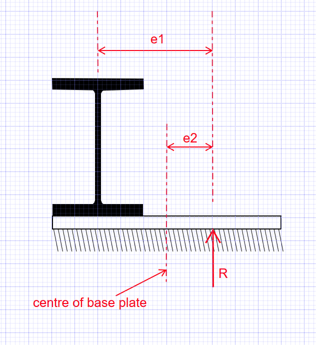
I have been thinking about the arrangement shown in the attached sketch which is essentially a steel beam with a steel plate welded to the underside of the beam. Both the beam and the cantileverng plate welded to underside of the beam are to support masonry.

It seems to me that the by extending the steel plate onto the support and providing a stiffener at the support the arrangement will be restrainted against rotation for torsional loading. However, I am not sure how to show it by calculation/prove it.

Would you have any thoughts on this?

I know that when it comes to lateral-torsional buckling, one of the conditions of restraint at supports is 'partial torsional restraint against rotation about longitudinal axis provided only by pressure of bottom flange onto supports'. This seems to show me that no additional fixings are requred in the above arrangement also when it comes to direct torsional loading but this is only my judgement.

[URL unfurl="true"]https://res.cloudinary.com/engineering-com/image/upload/v1609528948/tips/Steel_beam_with_plate_etdk7q.pdf[/url]
 
Replies continue below

Recommended for you

You need to fix the end supports against rotation if you plan to carry an eccentric load on the beam. The torsional moment at each end is R*e where R is the vertical reaction and e is its eccentricity. Your detail can work in theory because the load is not eccentric to the bearing area. But although the reactions can be accommodated, the steel beam has torsional stresses throughout the span because the load is eccentric to the axis of the beam.

Open sections are terrible at resisting torsion, but they may work if the torsion is not too large. You would be better to consider a closed section such as an HSS or double channels with channel separators space along the span.

BA
 
BAretired thank you for your post.

Do you mean that the torsional moment reaction at each support is basically half of the total torque acting onto the beam? Am I correct that in my case this will be just the eccentric UDL acting onto the plate (i.e. UDL2 in the figure attached) times eccentricity and times half the beam span?

[URL unfurl="true"]https://res.cloudinary.com/engineering-com/image/upload/v1609587970/tips/Torsional_moment_reaction_at_support_rs7kpm.pdf[/url]

It just came to my mind that the arrangement is really similar to an eccentric footing subjected to a moment. Running some numbers, stress under the beam and plate could be estimated (as in the attached).
Interestingly, assuming that the the beam total reaction acts through the beam web, there will be a constant pressure under the beam and plate. However, if the beam reaction is assumed to spread through the stiffener, theoretically part of the beam will not be in contact with support - this would be however not the case as the beam would be fixed to supporting padstone using locating bolt.

[URL unfurl="true"]https://res.cloudinary.com/engineering-com/image/upload/v1609588120/tips/Stress_under_plate_pxm1yy.pdf[/url]

Do you think the above analysis/reasoning makes sense or do you think some form of additional connection of the beam to supporting structure would be required (for example strapping the beam to support on the LFS to counteract the torsional moment)?

That's true that the open sections are not ideal under torsional loading, however, I have found that column sections most often work in these situations and are advantageous as they produce small vertical deflections.
 
In the sketch below, e1 and e2 are the eccentricities of the beam and base plate respectively. If e2 is within the kern of the base plate, there will be no uplift; otherwise, the pressure under the base plate will be triangular over a portion of the base plate.

In designing the beam, the eccentricity is e1; the torsion is R*e1. If the load is symmetrical over the span (UDL), then R = W/2 where W is the total load; otherwise, the end reactions would not be equal.

image_tc5z8x.png


BA
 
Pavel1234,

A W section beam resists torsional deflection under load like a well cooked spaghetti noodle. Please provide more information on your starting conditions and loading conditions. For example is this a point torsional load applied at some point on the beam or a uniform torsional load applied to the length of the beam or some portion thereof.

Please review AISC Design Guide No. 9 or similar manual for more information.

Jim

 
Pawel1234,

BARetired will steer you in the correct direction. His advise is almost always spot on.

Jim

 
Thank you for your replies.

BAretired said:
If e2 is within the kern of the base plate, there will be no uplift; otherwise, the pressure under the base plate will be triangular over a portion of the base plate.

BAretired, by saying 'within the kern of the base plate' I understand that you mean that the reaction is within the base plate (i.e. at least some portion of the base plate is in compression).

Following from that, if it can be shown that no uplift of the beam/plate occurs, do I understand correctly that if a strap was attached to top of the beam and then down to the supporting structure (please see sketch below), no tension would occur in the strap and so there would be no benefit in provide such a connection?

[URL unfurl="true"]https://res.cloudinary.com/engineering-com/image/upload/v1609680188/tips/Steel_beam_with_steel_strap_to_supporting_structure_ize4bj.pdf[/url]


jimstructures, the torsion acting on the beam would be in a form of uniform torsional load applied throughout the length. This would typically result from the plate supporting an external leaf of masonry/stonework and the beam supporting an internal leaf. I observe that for limited spans the W sections typically pass in such applications in rotation or stresses due to torsion. That said, relatively heave sections are required.

I'm comfortable with the torsion-related topics, however, I find that guides on torsion do not typically address supports for torsion in any great detail. As a 'real-life' support for torsion that is addressed by the guides I only seem to have found information on end-plate type connections. Therefore, I am wondering what you think on the idea of providing rotational restraint against torsion at the supports by extending the plate onto the support and providing a stiffener at this location (as shown in the sketch below that was included in my first post)?

[URL unfurl="true"]https://res.cloudinary.com/engineering-com/image/upload/v1609681426/tips/Steel_beam_with_plate_ioxrwk.pdf[/url]
 
Pawel1234 said:
I am wondering what you think on the idea of providing rotational restraint against torsion at the supports by extending the plate onto the support and providing a stiffener at this location (as shown in the sketch below that was included in my first post)?

Yes, because you have lengthen the support base, that offers better stability. If the stiffener is stiff enough (check buckling), and the resultant force/reaction falls within the kern of the lengthened base (as BA indicated, e2 = L/6), then there is no uplift, provided that the bottom plate is quite stiff too.
 
The kern of a rectangular area is the middle third.

If the c.g. of reaction R lies within the middle third of the base plate, the addition of a strap would have no effect on bearing pressure. The pressure would be in the form of a trapezoid running completely across the base plate and the strap would be unstressed.

If the c.g. of reaction R lies outside of the middle third of the base plate, then with no strap, the pressure distribution would be as shown on your sketch. Adding a strap prevents the slight rotation of the beam/baseplate assembly and causes tension in the strap. This increases the pressure between base plate and substrate and shifts the c.g. of the reaction force toward the strap, which alters the bearing pressure.

Instead of a strap, it would be more in keeping with usual practice to anchor the base plate into the substrate and to fasten the beam to the base plate with welds or bolts. It would be very poor practice to simply place the base plate loosely on the substrate.

BA
 
jimstructures,

Thank you for the tribute. I am indeed flattered.

BA
 
Status
Not open for further replies.

Part and Inventory Search

Sponsor