Continue to Site

Eng-Tips is the largest engineering community on the Internet

Intelligent Work Forums for Engineering Professionals

  • Congratulations KootK on being selected by the Eng-Tips community for having the most helpful posts in the forums last week. Way to Go!

Steel Bent/Cranked Beam 8

Status
Not open for further replies.

SarBear

Structural
Mar 14, 2022
38
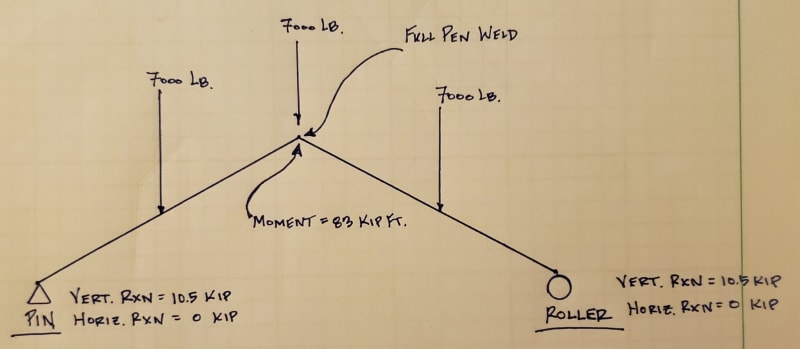
Hi all. I'm looking at a steel pavilion for a friend and am looking for some confirmation/guidance. I mostly work with wood-framed structures so this easy project is challenging me more than it probably should. As you can see below it is a pavilion with 3 steel a-frames/bents/cranked beams, whatever you want to call them. I have modeled the center one in Risa. It will be built with HSS tubes that weld together at the peak. My sketch below shows the pin and roller supports, the point loads from the purlins that hang into the a-frames, and the reactions at the supports. Here are some questions I have:

- Does my diagram make sense with the pin and roller supports?
- Does the 83 kip-ft moment at the ridge sound reasonable? I don't ever use Risa so I'm not sure I've modeled this correctly.
- How can I show that the full-pen weld at the peak can handle the 83 kip-ft moment?
- Any additional feedback would be appreciated
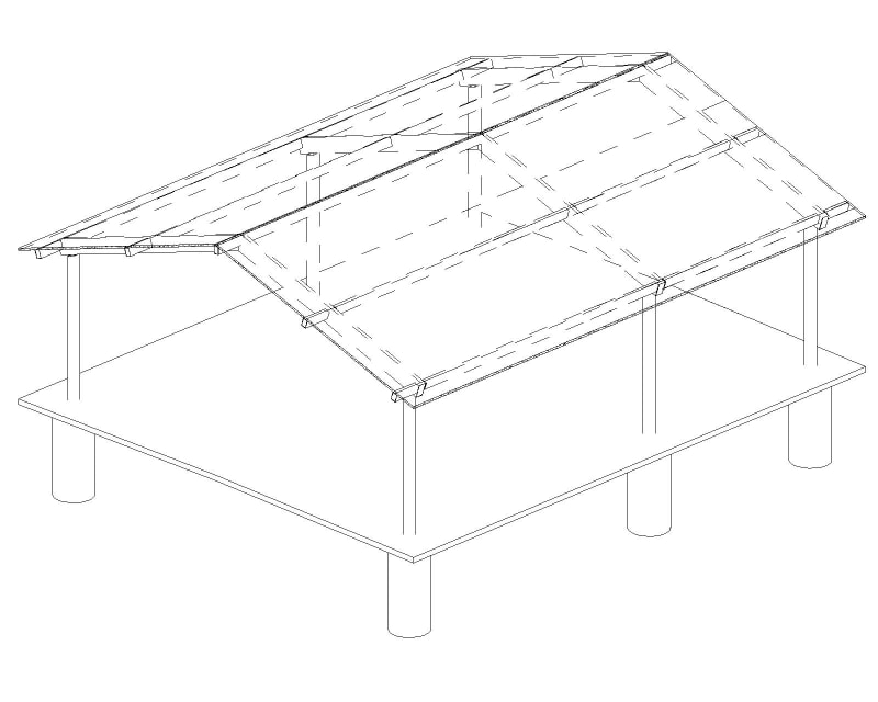
Pavilion_m3al2e.jpg
20240502_232815_azqady.jpg
 
Replies continue below

Recommended for you

You can beef up your cranked beam to provide a deflection that is within tolerance.

If you model just the A-frame with pinned supports you will get unrealistically high thrust forces.

If you model the columns with the A-frame, your thrust forces will decrease, and you will get more accurate deflections.

My recommendation is the following:

1. Design the beam as pin-roller
2. Model columns and A-frame together. Design columns for moment due to thrust (thrust force will be less than 19k) and check both horizontal and vertical deflections.
3. If your A-frame beam size is too large- you can look into accounting for some beneficial frame action. I would be cautious with this though because your column moment connection will be softer than the model shows.
 
you either need a tie to hold the thrust, or the columns take the thrust, or to install an actual sliding joint there.
 
canwest said:
Given the smaller eccentricity...it might be more rational to ignore it than in this case though.

I agree that channels will typically have less flange eccentricity but, even so, I feel that they may actually be worse than an equivalent HSS.

With an HSS, at least the flange can span out to the webs laterally as a simple span plate element. With a channel, in contrast, the flange has to cantilever which means that the flexibility of web comes into play (generally tall-ish and thin).

For the same volume of material, I'd feel better about an HSS12"x6" than I would a C12"x3".

The case of a stringer channel would actually create an unresolved twist without some form of roll bracing such as the stair treads.
 
Kootk, are you sure you get a twist?
I agree the channel web and flanges would bend, but I don't see twist coming into play.

It's easy to add a stiffener to the channel, whereas HSS welded to a plate is subject to lamellar tearing.
 
canwesteng said:
you either need a tie to hold the thrust, or the columns take the thrust, or to install an actual sliding joint there.
So my A-frame can't be designed as a self-contained structure that only places vertical loads onto the column? Please forgive my ignorance. I thought the purpose of the pin-roller design was to prevent thrust from being delivered to the column.


CDLD said:
1. Design the beam as pin-roller
2. Model columns and A-frame together. Design columns for moment due to thrust (thrust force will be less than 19k) and check both horizontal and vertical deflections.
3. If your A-frame beam size is too large- you can look into accounting for some beneficial frame action. I would be cautious with this though because your column moment connection will be softer than the model shows.
In #2 you are recommending that my columns be designed to take a moment into the base, correct?

 
EZBuilding said:
Why does a kinked beam cause weak-axis bending?

My interpretation of canwest's comment was that he meant weak axis bending of the flange itself, not the cross section as a whole.
 
CDLD said:
It's easy to add a stiffener to the channel, whereas HSS welded to a plate is subject to lamellar tearing.

Sure, it's easy. But it's very rarely done just the same. That, really, is the point that I was trying to make. This is something we do but do not have a robust method for doing.
 
CDLD said:
Kootk, are you sure you get a twist? I agree the channel web and flanges would bend, but I don't see twist coming into play.

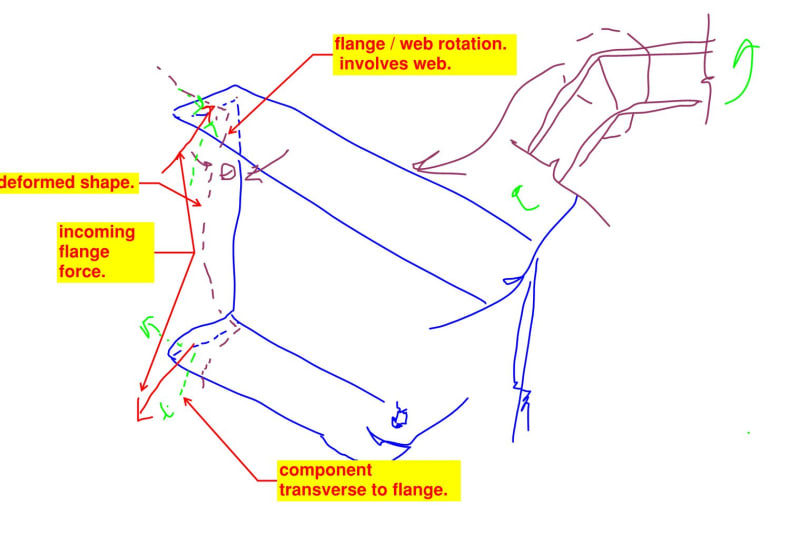
You're right. The model that I've been building in my head is shown below and the twist at the top and bottom flange offset one another, at least in the absence of consideration for second order effects etc. Thanks for the clarification.

I was kind of imagining the general, shear center offset thing with channels but that's quite independent of the kinked joint business, even if both effects would affect flange stresses concurrently.

c01_mljkit.jpg
 
SarBear said:
So my A-frame can't be designed as a self-contained structure that only places vertical loads onto the column? Please forgive my ignorance.
Yes, it can be designed this way. That is likely how I would approach it. In reality, the beam to column connection is stiffer than a pinned connection and less stiff than a fully fixed moment connection, but if it's not designed as a moment connection, I would expect it to be closer to that of a pin. And in this case, I would generally assume that any extra fixity is adding to strength.

Besides, you already did design it this way, but I think you determined that the vertical and horizontal deflections are not acceptable. With a deeper beam, that would solve that issue, just like if the beam had been flat.
 
SarBar said:
I just would like the A-frame to be a self-contained thing that only puts vertical load down onto the columns.

How are you providing lateral stability for the pavilion?
 
After reading the comment above by Celt83 I want to clarify that I made my preceding comment under the assumption that the overall lateral stability is being provided by some other means. Looking at the initial drawing, now I have the same question.
 
KootK said:
The model that I've been building in my head is shown below ...

...drawing...

So this gives reason to providing a plate between the beams as shown in human909's connection diagrams (b & d), no? Keeps the flanges from moving outward?
 
Eng16080 said:
I think you determined that the vertical and horizontal deflections are not acceptable. With a deeper beam, that would solve that issue, just like if the beam had been flat.
But what horizontal deflection is acceptable? In my mind it seems that any horizontal deflection at all won't be acceptable because it will rotate the post and its footing. Am I wrong?

Celt83 said:
How are you providing lateral stability for the pavilion?
The columns are 6x6 cantilevered steel columns.
 
Cantilevered columns are pretty inefficient but can probably get the job done for something like this.

What is your load path to get lateral loading into the columns? I’d imagine your “A” frames need to gather and transmit your main force wind so you’ll need to make sure you have that load case captured.

I would model the entire frame down to the foundation, for a cantilever column system that means releases at the “A” frame column joints this will give you the most realistic measure of the spread. If your software has the capability modeling your pier foundations as a series of horizontal springs will give a better approximation for a depth to fixity for the columns rather than simply giving them a fixed base connection in the model.

I would also give consideration to providing full bent frames inclusive of the columns for the 3 “A” frame locations for wind parallel to the frames and then consider them weak axis cantilevered for wind perpendicular.
 
I would probably design these as moment frames with pinned supports at bottom of columns, to avoid cantilevered columns (less efficient) and moment footings (more expensive). For the same reasons, I would probably design moment or braced frames at the eaves as well to avoid instability in the direction parallel to the ridge.
 
SarBear said:
But what horizontal deflection is acceptable? In my mind it seems that any horizontal deflection at all won't be acceptable because it will rotate the post and its footing. Am I wrong?
I would probably start by determining what vertical deflection is instead acceptable, and for that I would look at Table 1604.4 of IBC. It depends on whether there will be a ceiling finish and if so, what type of ceiling finish. Per that table, acceptable minimum limits are between L/120 and L/240 for total load. And for Snow, Wind, or Live load alone, they're between L/180 and L/360.

No matter what you do, there will be some horizontal deflection. Only in theory can it be zero, like if the column were infinitely stiff.
 
My experience with these has been that you really want to deal with the horizontal deflection by making the beam very stiff. Using cantilevered columns typically won't work.
By the time you make the beam stiff enough to limit the horizontal deflection (say 1/2" at the roller, which amounts to 1/4" each end in reality), the moments at the ridge are manageable, given the much larger beam size.
 
KootK said:
My interpretation of canwest's comment was that he meant weak axis bending of the flange itself, not the cross section as a whole.

That was also how I interpreted it and there was also the below comment by XR250

XR250 said:
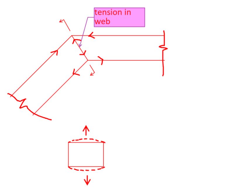
It is also necessary with high moments as kinked beams cause weak axis bending of the top and bottom flanges of the tube at the joint.

Was looking for some guidance on why there is weak axis bending of the flanges at the kinked joint - not able to picture it in my head...
 
EZBuilding, there is a tension or compression force in the web.
In the case of a cranked HSS, this force will bend the flanges.


Screenshot_2024-05-07_104108_sgsu29.png
 
Status
Not open for further replies.

Part and Inventory Search

Sponsor