Continue to Site

Eng-Tips is the largest engineering community on the Internet

Intelligent Work Forums for Engineering Professionals

  • Congratulations KootK on being selected by the Eng-Tips community for having the most helpful posts in the forums last week. Way to Go!

Steel Bent/Cranked Beam 8

Status
Not open for further replies.

SarBear

Structural
Mar 14, 2022
38
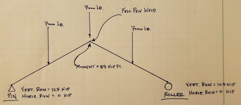
Hi all. I'm looking at a steel pavilion for a friend and am looking for some confirmation/guidance. I mostly work with wood-framed structures so this easy project is challenging me more than it probably should. As you can see below it is a pavilion with 3 steel a-frames/bents/cranked beams, whatever you want to call them. I have modeled the center one in Risa. It will be built with HSS tubes that weld together at the peak. My sketch below shows the pin and roller supports, the point loads from the purlins that hang into the a-frames, and the reactions at the supports. Here are some questions I have:

- Does my diagram make sense with the pin and roller supports?
- Does the 83 kip-ft moment at the ridge sound reasonable? I don't ever use Risa so I'm not sure I've modeled this correctly.
- How can I show that the full-pen weld at the peak can handle the 83 kip-ft moment?
- Any additional feedback would be appreciated
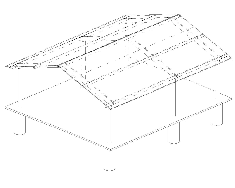
Pavilion_m3al2e.jpg
20240502_232815_azqady.jpg
 
Replies continue below

Recommended for you

dold said:
So this gives reason to providing a plate between the beams as shown in human909's connection diagrams (b & d), no? Keeps the flanges from moving outward?

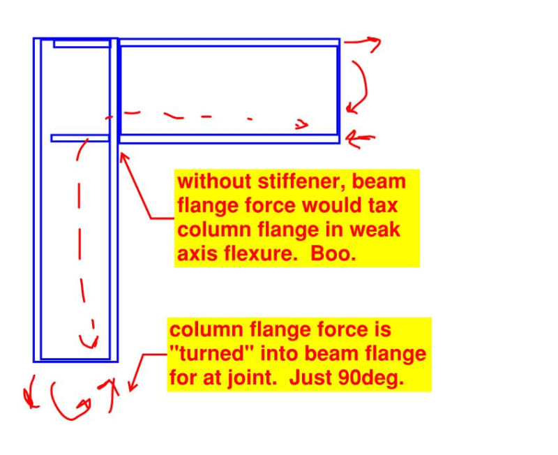
Precisely. This is one of the primary reasons for stiffeners in a lot of steel member moment connections: to change the direction of a flange force utilizing the in in plane stiffness of a stiffener rather than the out of plane flexure of the flanges. This is fundamental to robust steel detailing in the absence of concern for economy. Sometimes it's the way to go about achieving economy but not always (bolted end plate moment connections etc).

EZ said:
Was looking for some guidance on why there is weak axis bending of the flanges at the kinked joint - not able to picture it in my head...

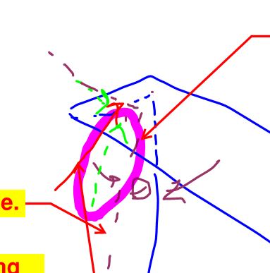
Ahh... I see. It's the force in my previous channel sketch circled in purple below. If you imagine the channel sketch as just half of a tube, it's pretty much the same thing.

c01_snwpsc.jpg
 
With respect to my comments in my previous post, I think that it's useful to remember that this same business of trying to avoid weak axis plate flexure in mitered HSS and channel moment connections is conceptually no different from the much more familiar case shown below. Somehow it's just a lot easier to visualize with orthogonal WF.

c01_mk04el.jpg
 
I disagree on calling this equivalent to a flat beam. There will always be some thrust that wouldn't occur if it was a beam, and this needs to be accounted for in the columns or they may be overloaded in some cases.
 
canwest said:
I disagree on calling this equivalent to a flat beam. There will always be some thrust that wouldn't occur if it was a beam, and this needs to be accounted for in the columns or they may be overloaded in some cases.

Is that in reference to my latest post or other stuff?
 
Just relating to the ongoing discussion on how to analyze the frame itself.
 
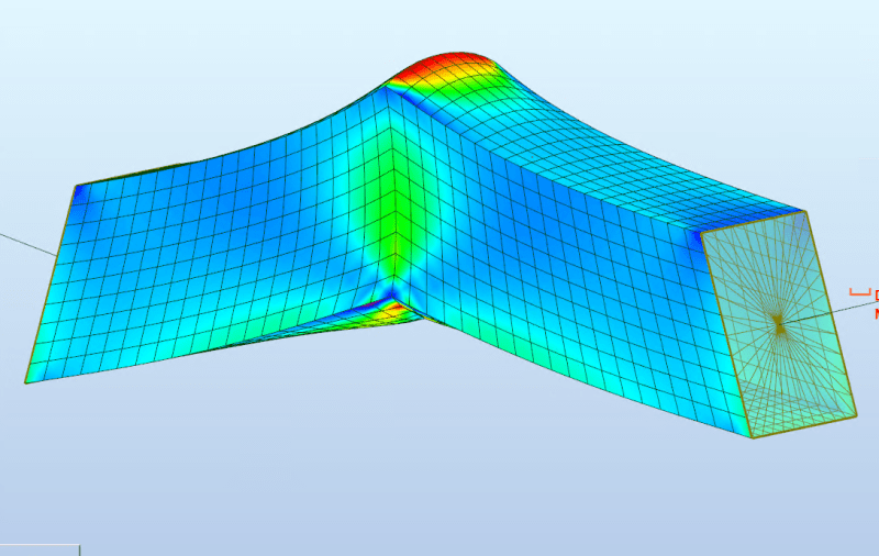
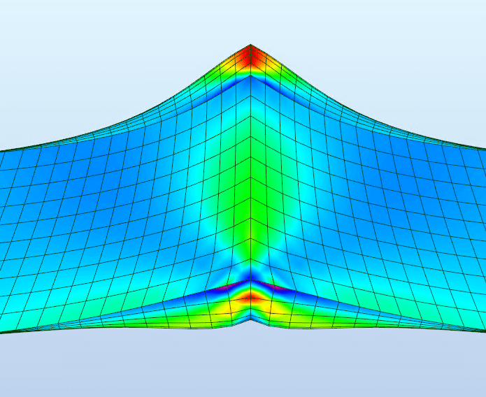
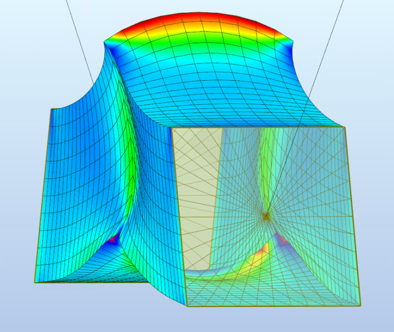
EZBuilding I had trouble visualizing it myself and for S&G's popped it into a 5 minute model this has the deformation significantly amped up but you can see the top and bottom walls bulging outward and the side walls collapsing inward:
Screenshot_2024-05-10_120834_igfne8.png

Screenshot_2024-05-10_121753_lc3zik.png
Screenshot_2024-05-10_121725_ldehv4.png
 
canwest said:
I disagree on calling this equivalent to a flat beam. There will always be some thrust that wouldn't occur if it was a beam, and this needs to be accounted for in the columns or they may be overloaded in some cases.

It's based on the OP's assumption of pin/roller supports.
 
CDLD, KootK and Celt83 - thanks to all for that input. The comparison to the stiffener plates on a beam/column moment connection was helpful, as was the FBD showing the unbalance tension/compression resultants of the moment at the peak. The FEA output was also great!
 
KootK said:
Quote (SarBear)
From most of your comments I get the vibe that there isn't really an actual calculation for the moment capacity of my connection at the peak.

I think that's an accurate statement as far as unstiffened moment connections go. It's a pretty common thing for designers to want to do this on smaller applications but, to my knowledge, there is no industry sanctioned design method for dealing with it. A great many dog legged stair stringers are examples of this in my experience.

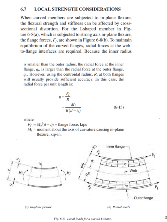
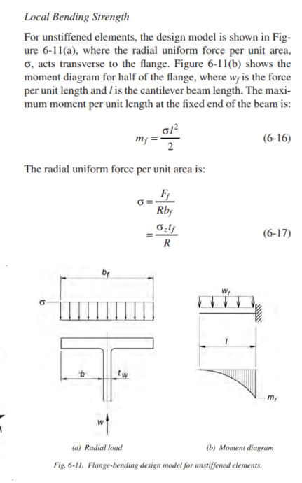
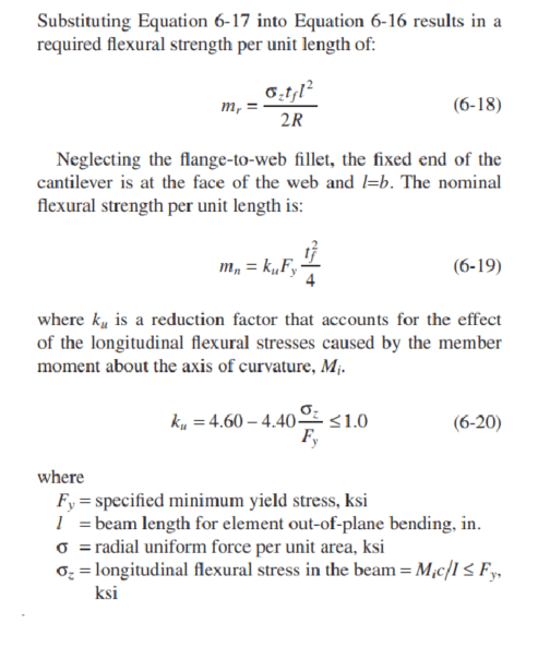
I think I may have found a suitable design method in ASIC DG 33 "Curved Member Design".
This DG is intended for vertically curved members, however I believe the provisions could be applied to the joints of cranked beams.
The DG provides methods for calculating the local flange bending (and its interaction with longitudinal stresses) as well as web stress.

Screenshot_2024-05-14_092356_ixbcny.png


Screenshot_2024-05-14_092452_vq9t9l.png


Screenshot_2024-05-14_092529_hcanzc.png


I've only posted the flange bending for I-shapes; in the DG you can find guidance for tackling HSS as well as local buckling of the web.
 
Status
Not open for further replies.

Part and Inventory Search

Sponsor