Continue to Site

Eng-Tips is the largest engineering community on the Internet

Intelligent Work Forums for Engineering Professionals

  • Congratulations KootK on being selected by the Eng-Tips community for having the most helpful posts in the forums last week. Way to Go!

Steel Column Base Repair 1

Status
Not open for further replies.

yhjinkim

Structural
Jan 28, 2008
2
Hi, I'm working on a repair project for some of the warehouse steel column bases.

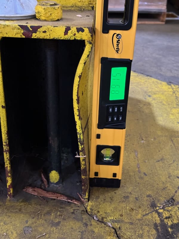
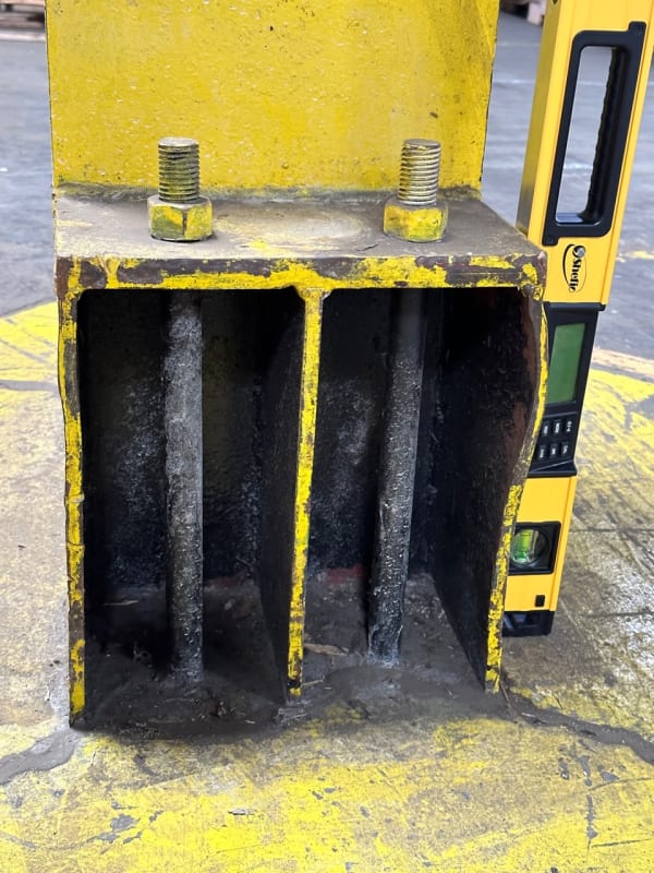
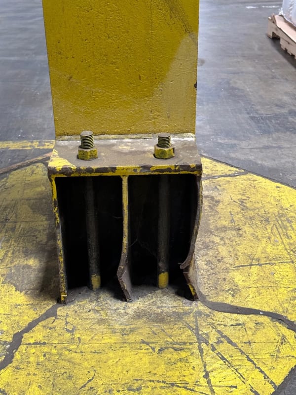
The columns are W12(12"x12") and there are three vertical stiffener plates and a cap plate welded to the both sides of the W12 columns. The column bases are heavily damaged by forklift as attached.

I first thought that the damaged plates need to be removed and replaced. But my boss thinks that the stiffeners are for seismic or lateral resistance with a 1" gap shown on the detail (see pdf file). So, the stiffeners should be continuous without cutting and he suggested that the steel plates need to be heated and be straightened up and then some weld pieces be added to the torn plates.

Looking at the detail on the pdf file, I think the baseplates should be exposed and the bottom of stiffener plates be above the finish floor, rather than embedded into the concrete. If the stiffener plates are partially embedded, what's the purpose of the gap?

Does anybody have worked on this type of connection repair? Can you share me with any insights on this? Thanks!

YK
IMG_1577_wlasvm.jpg
IMG_1616_v87pt0.jpg
IMG_1582_dk1h5g.jpg
[URL unfurl="true"]https://res.cloudinary.com/engineering-com/image/upload/v1685042998/tips/column_base_v0s3wc.pdf[/url]
 
Replies continue below

Recommended for you

I like your boss' suggestion to leave the existing stiffeners and weld new. The column baseplate looks like it is buried within the concrete so the stiffeners facilitate chairs to give the anchor bolts stretch length for ductility. When you do this, however, you loose a good amount of shear capacity, but perhaps for this interior case you wouldn't need to worry about that. The stiffner portion that is buried in concrete is braced -- I'd just repair the portion above the TOC.

"Engineers only know about 80% of the truth, the next 10% is very difficult to achieve, and the last 10% impossible. If we are bound to be wrong, we may as well be wrong simply and conservatively."
 
The stiffeners are providing a stretch length for those bolts. Which implies that the column is part of a lateral system. Whatever the total tension in the two bolts is needs be carried by the stiffener plates all the way down to the column baseplate in compression.

I'm not seeing how the stiffener plates would improve the shear anchorage of the baseplate. If anything you might say they improve the shear strength of the column, but that is not the typical way to reinforce a WF section for shear, and it seems unlikely to me that this would be a shear controlled column.

As far as repair, I would look to determine the anchorage force on the two bolts, and re-stablish the compression load path down to the baseplate. I would be probably adding a new full height stiffener on both sides and welding it to the baseplate below TOC.
 
@yhginkim

Given this is an interior column, I doubt there is much if any shear at the base or even moment -- is this acting as part of the LFRS from the framing configuration that you see? The baseplate which is buried below the concrete is taking the column compression load, not the anchor bolt / chair assembly. For uplift, the stiffeners would engage but at that point I wouldn't be worried about buckling on the plate section at all.

"Engineers only know about 80% of the truth, the next 10% is very difficult to achieve, and the last 10% impossible. If we are bound to be wrong, we may as well be wrong simply and conservatively."
 
I suppose you could add new plate only above the TOC then take all the compression in the plate out on the edge that is welded to the column. Kind of like a triangular bracket seat. I am concerned about those stiffeners being able to do their job (compression) now that the cross section is disturbed.
 
@driftLimiter

Where are you seeing this compression load in the stiffeners? It looks to me that this chair assembly is welded to the side of the column and does not participate in the compression load distribution. If indeed a lazy column, the only force those stiffeners will see is tension. I like your solution to chip out the concrete and weld the stiffeners to the baseplate but that is invasive and not sure it's merited.

Nice chatting alongside you in a couple of threads the last few days -- what area do you work in?

"Engineers only know about 80% of the truth, the next 10% is very difficult to achieve, and the last 10% impossible. If we are bound to be wrong, we may as well be wrong simply and conservatively."
 
Look at the interface from the bolt head and the top of the chair. In order for the bolt to be in tension, the chair must push back up on it.

I'm out west in old high seismic high snow high wind country lol.
 
@driftLimiter

This is true..oh those poor nuts that are about to pull through the chair. My gut tells me there probably isn't much uplift to transfer into but you're right about the compression.

The stiffener below the concrete is continuously braced so it cannot buckle..I'd just check the portion above and reinforce that. Like I said cutting out that concrete is extremely invasive.

Nice to meet you -- I'm the other way, out east!

"Engineers only know about 80% of the truth, the next 10% is very difficult to achieve, and the last 10% impossible. If we are bound to be wrong, we may as well be wrong simply and conservatively."
 
80percenttruth said:
Given this is an interior column, I doubt there is much if any shear at the base or even moment

Moment or braced frames definitely exist in the interior of buildings.

80percenttruth said:
Where are you seeing this compression load in the stiffeners?

The stiffeners are generally used to stiffen the baseplate and not the column. The compression load comes from the moment at the base of the column. Assuming this is a moment resisting baseplate (because this would be a pretty common MR baseplate design) then the compression in the stiffeners would be proportional to the total tension in the anchor bolts on the opposite side of the baseplate. Not necessarily the same value since not the entire compression load is resisted by the cantilevered portion of the baseplate - some is resisted by direct compression under the column flange.
 
Isn't the load path: tension in the bolts, compression in the horizontal plate, then stiffener plates transfer that load via shear into the face of the column? I have only used these when the uplift force is so great you would need too thick of a base plate to work as a cantilever in bending, so this connection transfers all of that tension up into the face of the column via shear.

Then can't you just put new stiffeners above the horizontal plate? Then as Dold said, you could design the connection for the capacity of the bolts to be conservative.
 
yhjinkim said:
I'm working on a repair project...

The column bases are heavily damaged by forklift...

...my boss... suggested that the steel plates need to be heated and be straightened up and then some weld pieces be added to the torn plates.

[thumbsup2]

... and steps taken (by you or others) to prevent forklifts from impacting/damaging the repaired column in the future.

 
Thanks for the responses, everyone. We decided to straighten up the damaged plates and weld new.

Have a great long weekend!
 
Status
Not open for further replies.

Part and Inventory Search

Sponsor